How to control a load with a digital circuit like Arduino? A transistor relay circuit may be answered for you.
The output pulse from the digital circuit to biased the transistor is ON.
Then, it drives the relay as a switch ON-OFF. To power to any circuits or external devices.
Basic Application Relay
The Controlling electronic circuits, Electrical devices in homes or factories. We often use the relay, first. Though they are very ancient, relays still have many uses. Because it is easy and cheap.
A general Relay is a mechanical switch. Its contact is closed when a current flows through a coil.
On the circuit diagram below is a simple basic circuit. You will understand the working of a relay.
A smaller voltage (V1) is the maximum voltage that the coil can get it. There is a lower-current I1 flow through R-resistor. It limits current to a safe level for the coil.
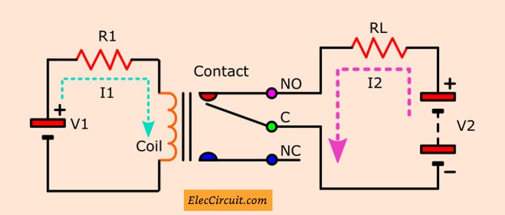
Thus, when the current flows through the coil. Then, a magnetic field occurs. It makes the contact of relay connect together as a switch is closed. To connect the voltage-V2 provides a high current (I2) to Load as we need.
Sometimes you may use the relay with a digital circuit. Using the output pulse from a microcontroller or digital gate ICs. To control relay to works.
But the most, its output is low current. So you need a helper, use a transistor to switch high current to drive the coil instead.
Most transistor relay driver circuit
In the circuit below is most transistor relay driver circuit. The coil of relay needs a current about 100 mA. And, the input current at output of a normal digital circuit is about 2 mA.
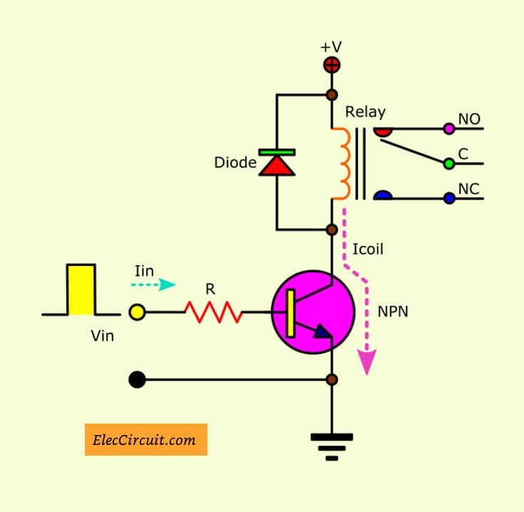
You can calculate a limiting resistors-R from the input voltage and current. For example, input voltage of 5V, Current of 2 mA approximately.
Thus, You can calculate R as follows:
R = (Vin-VBE)/Iin
Vin = 5V, VBE of a silicon transistor is about 0.7V, Iin = 2 mA
R = (5-0.7)/(2mA)
= 2,150 ohms
Thus, we should select R = 2.2 K. It is the standard value. You can buy it any stores.
VBE is a voltage across at base-emitter of a transistor.
What is the transistor number?
In the circuit above, Here is how you can choose a proper number. First, It is an NPN transistor type.
Suppose the transistor has a currents Gain (hFE) about 50 times. Since the input current is about 2 mA. So, get current out of the output is about 100 mA (2×50 = 100). It is enough to the needs of the relay coil.
There are a lot of transistors that have the hFE gain is more than 50. For example, 2N3053, 2N2222 transistor, etc.
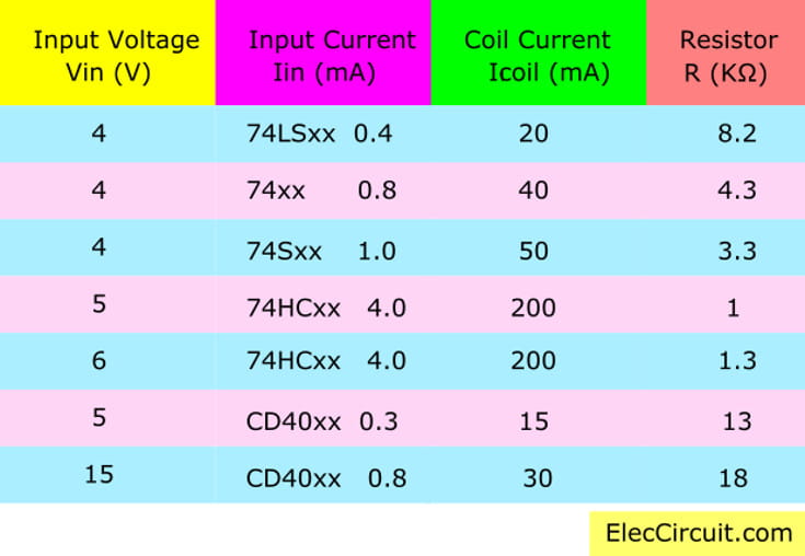
Then, Look at Table: 1
They show the size of any value.
- Vin—input voltage
- Iin—output current of ICS
- Icoil—current of a Relay coil
- R—limit current resistor
Table 1 shows size of input voltage of various digital ICs and the relay coil need. By has various resistor-R limit proper current for circuit.
The relay coil is get from input voltage
Figure 3 is the driver relay circuit by use input voltage to feed to the relay coil but has some voltage junction base and emitter lead of transistor. Which has value about 0.7 volts.
For example input from the pulse output digital pulse of 12 volts to drive to the transistor.
Therefore, we will have voltage across the relay coil about 12V-0.7V = 11.3V, etc.
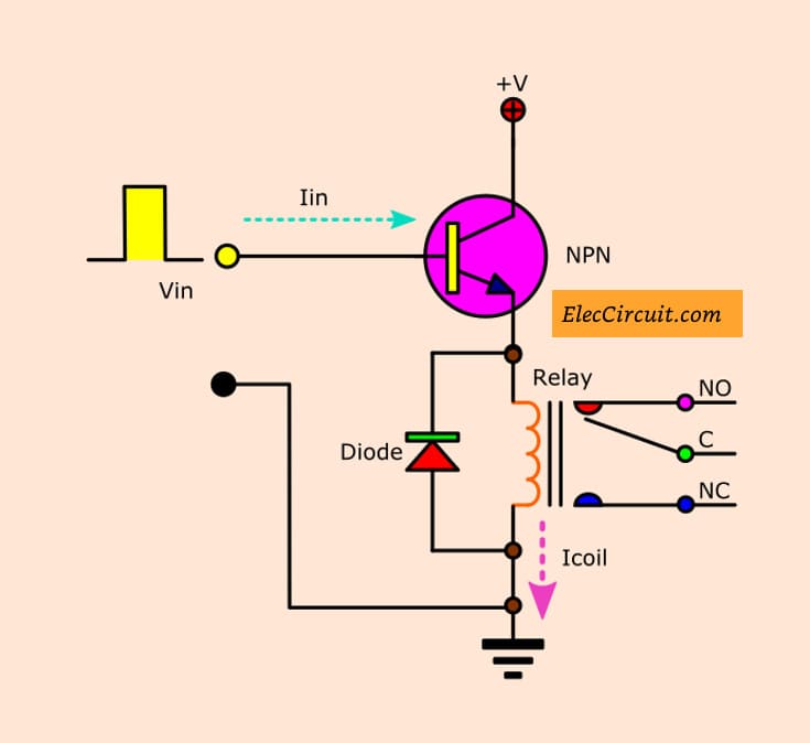
Figure 3
This circuit does not require a resistor-R. Because the circuit as emitter follower will have a high input impedance already.
So do not worry that the noise came as a result, the transistor works, the input current “Iin” calculated by the current flowing through the relay coil divided by the gain of transistor.
Such as resistance of the relay coil equals 120 ohms.
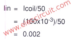
Which we use transistor has gained is 50 times will calculate the “Iin” below:
Iin = (100×10/-3)/50
= 2mA
Therefore, it calculates the current input equals: 2 mA.
On each relay feature will is determined the resistance of the coil is ohms unit. So if we know the voltage of the relay will also calculate the current of the coil. such as a voltage of the relay is 12 volts.
The resistance of relay coil 120 ohms will calculate the current flowing through the relay coil is 12 divided by 120 equals 0.1 A or 100 mA etc.
How to increase the gain
Figure 4 is the relay driver circuit that has increasing gain up. In case that very low input current from a digital circuit. We will see that this circuit we use the transistor as a Darlington compound to replace two transistors.
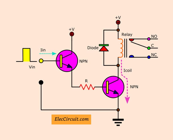
Figure 4
If we use a transistor that has gained about 50 times and use one transistor to increase up to 2500 times (50×50). Thus, if very low current about 100 uA, the relay driver circuit can provide current up to 250 mA

Therefore, the current coil of 250 mA.
The resistor-R can be Calculated by input voltage, input current, and gain of the first transistor.
For example, input voltage-Vin equals 5 volts,
the input current-Iin = 100 uA and gain of the first transistor is 50 times will calculate the “R” as follows.
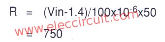
Therefore, resistor-R was calculated by using the 720 ohms or 750 ohms instead.
(A value of 1.4 is the voltage drop across the base and emitter lead combination is measured in volts.)
The Reverse state Relay Driver
Figure 5 is a relay driver circuit. Which will works the opposite of all the circuit?
Because the circuit in Figures 2, 3 and 4 will run. When the output from the digital circuit is fed into the input is high state or logic “high”.
But in the case of Figure 5, the reached input into a low status or logic “low” to make transistors works to drive a relay.
Notice that there are resistors on the 2 pcs. Using resistor-R. It is calculated as the circuit in Figure 2.
The resistor-R1 to be high enough to be worthy before causing the voltage across the collector and emitter of first transistor saturation.
And must have a low value, before it causes the second transistor, the state of saturation.
This means that despite the change in the input current will not affect the output currents.
You may also like these:
Example: Relay 12 volts requires current flow through relay coil 100 mA, by use transistor that has gained 50 times, thus will calculate the input current as follows.
Therefore the input current-Iin paid to second transistors equals 2 mA is current, that makes first transistor saturation occurs at voltage 12 volts.
Thus, the R1 will be less than the calculated value. Here, the R1 will be less than 6 K ohms (calculated by dividing the voltage of 12 volts with a current 2 mA).
And if the first transistor has gained is 50 times has input current-Iin = 100 uA Therefore the current flowing through R1 is equal to 5 mA.(Calculated by 50 multiplied by 100 uA).
It is the current value that would make the state second transistors a saturation voltage of 12 volts.
Therefore, the R1 will be greater than the value calculated in this R1 will be more than 2.4 K ohms. (Calculated by dividing the voltage 12 volts with a current of 5 mA).
The resistor-R1 are in the range of 2.4 to 6 K ohms, which is suitable to be used is 4.3 K ohms, is centered correctly to keep both transistors work before the saturation.
All of the above circuits Be noted that there is a diode across the relay coil. To prevent reverse voltage from the induced magnetic field of a relay. This makes the transistor is damaged. The most diode will be diode that is in the general rectifier circuit is 1N4001 etc.
All the relay driver circuits above are the pulse output of the digital circuit to control a transistor works and drive relay as an ON-OFF switch for circuit or external devices next, to using it now selected to suit the circuit.
Recommended: How does an SCR work
How to boost up voltage for low voltage Relay
Using relay general the majority than to use a power supply that has DC Voltage with the value volt that specifies on a relay.
For relay work but, if, we have no power supply that wants to feed give relay. This circuit helps to give relay can work.
How the circuit works
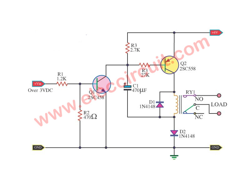
From the circuit uses two power supply from at for come to work give Relay 12V work.
The power supply first uses 6Volt when feed volt come in touch C1 charge take keep.
The power supply that 2 uses voltage more than 3V feed comes in the way input makes Q1 work.
It makes Q2-BC558 work go to with be make C pin of Q2 have voltage source 6V feed give relay Ry1 and When Q1 work will be compared as something through the circuit down the ground.
It makes C1 do something discharge 6Volt come out of the cathode of capacitor C1. Which builds with a pole of relay RY1 again beside one makes have drop voltage relay RY1 equal to 12V.
Then make relay RY1 work and will work long ago only? that depends on something discharge of capacitor C1.
Replace Part: BC558 = BC327 = BC556 = 2N4403 PNP 40 Volt 0.6A
2SC458 = 2SC1815 =2SC828 = 2SC2675 = BC337 = 2N2222
Related Posts


I love electronics. I have been learning about them through creating simple electronic circuits or small projects. And now I am also having my children do the same. Nevertheless, I hope you found the experiences we shared on this site useful and fulfilling.
I am aiming to get heat in the range of 45 deg. to 50 deg in my small Incubator.
and if possible, please provide me the coli type that I should use.
and the relay type
thanks ..