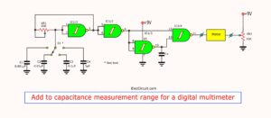
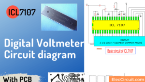
Today, I recommend the digital capacitor meter projects. It can measure capacitors ranging from 1pF to 2,000 uF. Which covers almost all of the capacity. And cheaper, it’s much more effective than Simple capacitance measurement. And continue to develop this project(digital voltmeter).
Usually, we use the digital multimeter cheap. Can measure only the capacitors 20uF only. But when we need to measure the capacitance value than that. We need to use the digital capacitor meter specifically. Which can be measured with a high-capacity 2,000 uF. As this project. We can build your own. To save and gain experience of good electronics.
Operation of the circuit.
The working simple principle of this circuit Will be seen that the circuits consists of two main parts are
The trigger and monostable circuit.
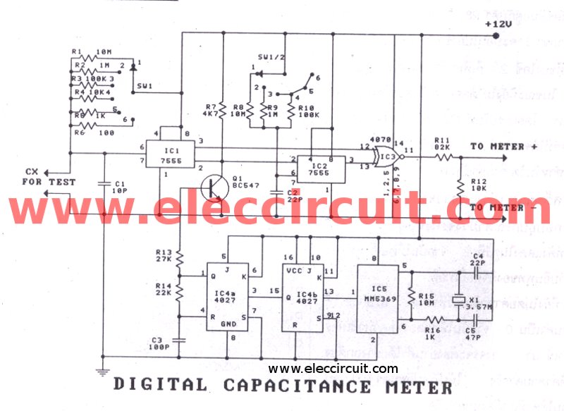
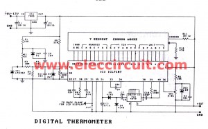
Figure 1 the circuit diagram
The trigger circuit consists of IC-5(MM5369) and IC-4(CD4027). The IC5(MM5369) will generate the clock signal that has frequency of 60Hz. Which Which is the time between the trigger pulse of 16.6 mS. When applied this output is fed to a pulse with a time IC4b 33.3 mS.
IC4a (CD4027) served as the monstable to determine the output pulse range of the R14, C3.
Because the output pulse from IC4 is the positive pulse. Therefore, we need to reverse the negative pulse with Q1-transistor(BC547)
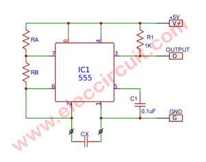
The IC1(LM7555) is a monostable circuit. The width of the output pulse depends on the value R1-R6. Which serves as options of range measure. and capacitance that bring the check.
Learn: How to use 555 timer circuits
When the trigger pulse from Q1, Will be the output pulse that has a width depending on value of Cx, into pin 3 pass through the X-OR circuit. The IC3-CD4070 applied the output signal at pin11. enter to a R11-resistor into input of the digital voltmeter.
The IC-2 is the monostable. which will be the width of the pulse depends on the French R8, R9, R10 and C2. The output pulse from pin 3 is input to pin 13 of IC3.
Function of IC2 (LM7555) to customize the circuits read is 0. While not connected to the capacitor to the circuits. By adjusting the C2 provide pulse. Of IC2 equal to pulse at IC1. output while not connected to the capacitor for check has a value of 0.
To build and customize circuits.
All circuit assembly according to the PCB, as shown in Figure 2. And Figure 3 is a positioning device. Then, connect the output of circuit into input of the digital meter.
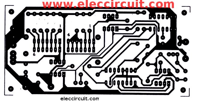
Figure 2 The PCB of this projects
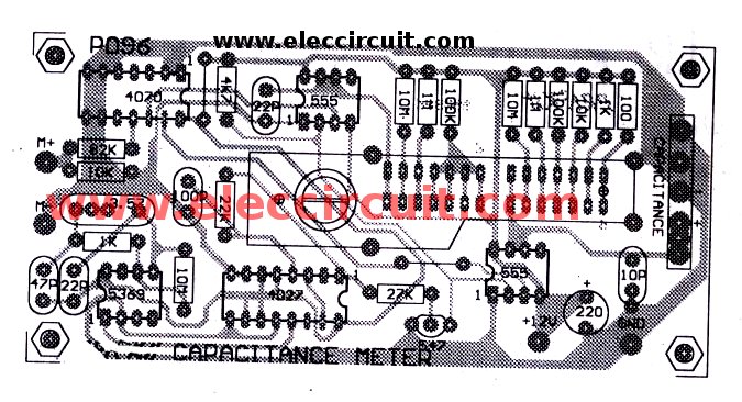
And Figure 3 is layout of PCB
While it is not connected to the capacitor, Adjust the C2 to the meter reading is 0. then try to connect the capacitor that know value into. The circuit will be read correctly. If not by the actual value. Adjust R11 until the meter reads the correct all range.
Detailing equipment
IC1, IC2: LM7555 timer
IC3: CD4070 Quad 2-Input EXCLUSIVE-OR Gate
IC4: CD4027 CMOS Dual J-K Master-Slave Flip-Flop
IC5: MM5369 MM5369 17 Stage Oscillator/Divider
Q1: BC547 45V 100mA NPN Transistor
1/4W +/- 1% Resistors
R1, R8: 10M
R2, R9: 1M
R3, R10: 100K
R4, R12: 10K
R5, R16: 1K
R6: 100 ohms
R7: 4.7K
R11: 82K
R13: 27K
R14: 22K
R15: 20M
The ceramic capacitor
C1: 10pF 50V
C3: 100pF 50V
C5: 47pF 50V
C2, C4 (TRIMMER): 22pF
C6: 220uF 16V Electrolytic Capacitors
X-TAL: 3.579MHZ crystal.
S1: SW.2 step 6 way switch
Related Posts

I love electronics. I have been learning about them through creating simple electronic circuits or small projects. And now I am also having my children do the same. Nevertheless, I hope you found the experiences we shared on this site useful and fulfilling.
I have Requard capacitor cheak meter.
Can you please explain how you found out what values you needed for the capacitors and resistors. I want to be able to understand the logic behind this circuit.
Is the six way switch a double pole – this is not very clear in the parts list, and what range do we set the dmm to
Regards Kris.