Do you want a sawtooth generator circuit diagram? We have 3 circuits for you.
The first circuit is easy and has a few parts. The second circuit is the Ramp generator is similar to the first one. Lastly, using a CMOS IC: Current-controlled Sawtooth Generator Circuit.
1. Sawtooth generator circuit using transistors
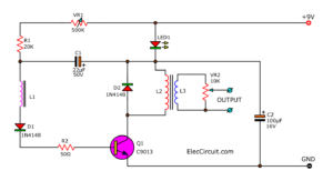
This is a Sawtooth wave generator circuit using UJT transistors is easy. In the Figure 1 circuit used Q1 is UJT to connects with VR1(potentiometer), VR2 and C1. They act as a sawtooth wave generator circuit, by C1 to charge and discharge.
Then, current from the 5V power supply through VR1 and R2. This current and voltage that increase and reduce, cause Q1 to generate a signal. Which have the sawtooth wave signal or the ramp signal to the output, which frequency is determined with R, C as above.
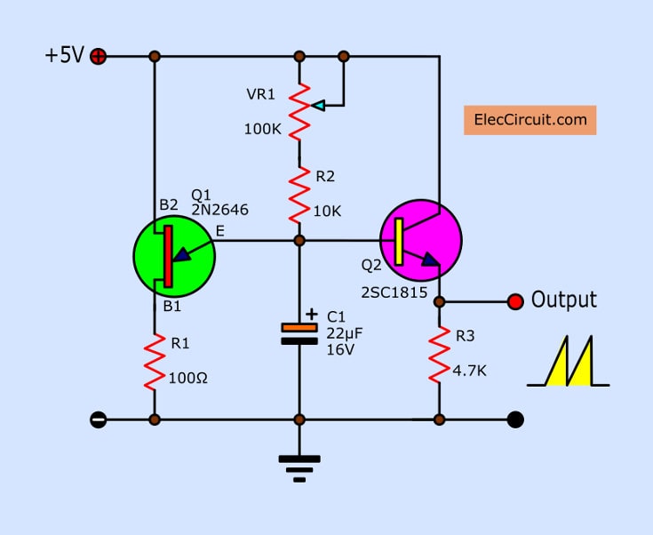
When Q2-transistor is derived the signal input to conduct current as the sawtooth signal voltage by at pin E of Q2 will be connected into the output signal that has voltage from OV, then partially rises by slop up to +VCC of 5V is sawtooth waveform.
When C1-capacitor discharge voltage that enters to Q2 will reduce until cause Q2 stop conduct the voltage at pin E of Q2 so make signal out of Thus making output signal continuously as well. And in between at C1 discharge are pin B1 of Q1. It is a short positive pulse occurs as well. Which can be used to provide input to the device. To control the operation again.
How to build
You can put all parts in components layout on universal PCB board as Figure 2. What to check carefully for the polarity of the electrolytic capacitors and Diodes correctly. Pin of the Q1-UJT, Q2 is not an error.
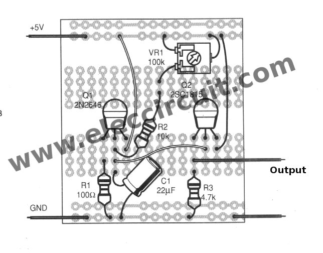
Figure 2 The components layout on the universal Board.
The components List
Resistors ¼W +5%
R1: 100Ω
R2: 10K
R3: 4.7K
VR1: Potentiometer, 100K
Capacitors
C1: Electrolytic 22uF
Semiconductor
Q1:2N2646 UJT, Silicon unijunction transistor
Q2:2SC1815 or equivalent, 0.1A_50V NPN Transistor
2. Ramp Wave generator using 2N4891
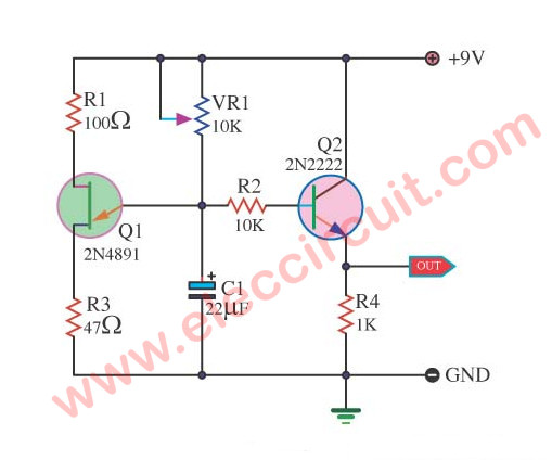
This circuit is like the above circuit. There may be another way for you. Also, use UJT is main, 2N4891. The peak voltage output is about 5.4V if use power supply Voltage of 9V.
3. Current-controlled Sawtooth Generator Circuit
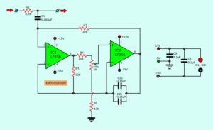
This Sawtooth wave generator circuit include of the frequency oscillator is controlled by current. Which can generate the sweep frequency in a wide range. Suitable to be applied in the field of music equipment and narrow pulse output. Also, we are able to be a random circuit and Hold.
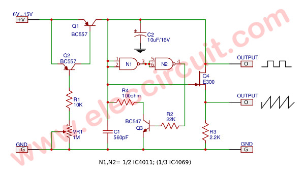
This circuit include of current variable power supply circuit (T1, T2-BC557) and trigger (N1, N2 of CD4011) and switch (T3-BC547). When applying voltage to the circuit, C1 will be charged by current sources. Then, the voltage across C1 to the threshold level of N1.
The T3 is conducted current, through N1 and N2, and C1 is discharged. After all, the cycle will start automatically. The sawtooth waveform at the output will be buffer by FET(E300). The T4 is the peak-to-peak signal of about 1.3 volts.
The value of the equipment specified in this circuit, it is frequencies about 5 to 500KHz, by adjusted by P1, although the circuit is able to output at high frequencies. But it would have distorted waveforms.
If C1 = 5.6 nF and R1 = 1K frequency is in the range of 0.5 to 500 kHz And may be used the inverter replace the NAND gate.

Related Posts


I love electronics. I have been learning about them through creating simple electronic circuits or small projects. And now I am also having my children do the same. Nevertheless, I hope you found the experiences we shared on this site useful and fulfilling.