This is a 12V stable battery voltage regulator circuit using MC34063. We use it to a 12V battery. Its output voltage is steady at 12V. Although the input voltage change between 5V and 13V.
It is a switch mode power supply. Thus, it has high efficiencies of over 90%. In the circuit below, it uses the MC34063 and a few components. So we can build easily with cheap.
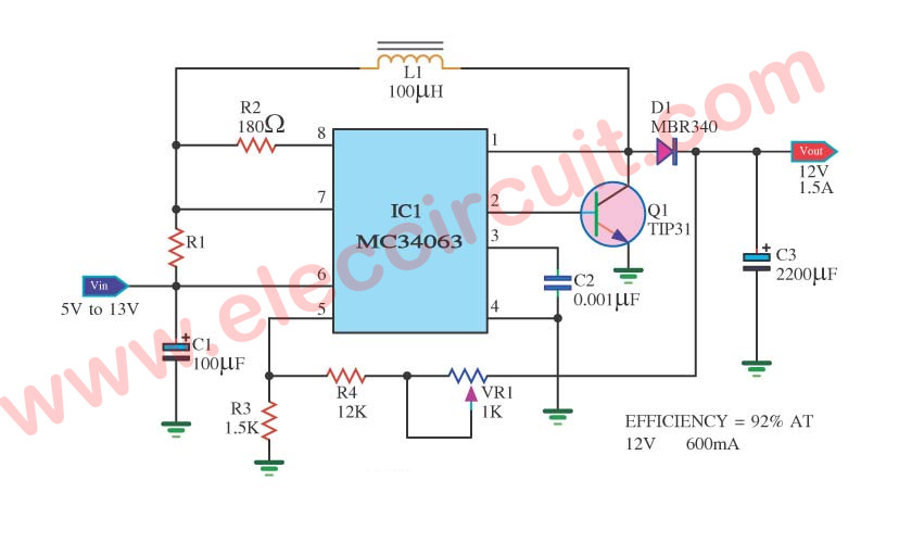
Use IC- MC34063 so easy circuit, Adjustable VR1 for Control Efficiency at 12V 600mA
The MC34063 is a very useful chip. It is a DC-DC converter chip. We can use it as a buck converter, a boost converter, or an inverter.
Thus it can function as a step-up converter, a step-down converter. And the inverter with a combination of step-up or step-down function.
Often we found it on many devices such as car chargers for instance to regulated voltage levels.
The MC34063 can operate on the input voltage of 3V-40V and the output voltage is adjustable.
Its output current capability up to 1.5A.
And it can switch power at frequencies up to 100KHz.
The datasheet for the MC34063 chip. We can see at the following link: MC34063 Switching Regulator Datasheet.
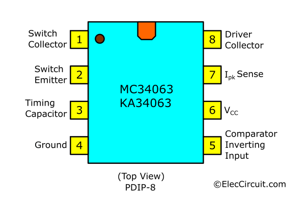
It is an 8-pin chip. Thus, it is small in size same as IC-555.

The MC34063 pinout.
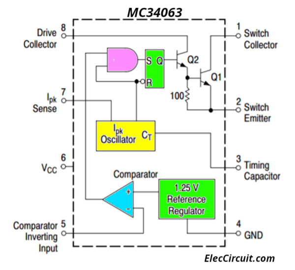
Basic internal circuit structure
Recommended: Recycle Free Li-ion battery from E-waste
Working of Circuit
In the circuit above. This circuit uses a few components. We come to see it.
First of all, to power this chip with connecting +V to VCC pin 6, and the pin 4 to ground.
Next, this sets power for the chip. After that, the input voltage, to VCC and ground. At the same time, we connect a 100uF capacitor. It will filter an excess noise from the power supply out.
Then, Pin 2 connected to the base of internal transistors-Q1-TIP31 to ground.
Pin 3 is the timing capacitor-C2. It determines the switching speed of the circuit.
Pin 5 is inverting terminal of the comparator.
The voltage of the non-inverting terminal is 1.25V from the internal voltage regulator.
To the inverting terminal, we place a resistor network composed of 2 resistors. These decide the gain of the op-amp comparator by the formula, VOUT= 1.25V (1 + R4/R3).
Since we want an output voltage of 12V, R3= 1.5K and R4= 12K.
We use the potentiometer-VR1 to adjust the Efficiency at 12V 600mA
This is how the circuit has its boost functionality.
And this is a classic switch mode power supply using the MC34063 chip to act as a step-up or boost converter.
MC34063 circuits
We can use MC34063 to make many circuits. See the circuits below, you will see other ideas.
Step-up DC Boost Converter circuit using KA34063
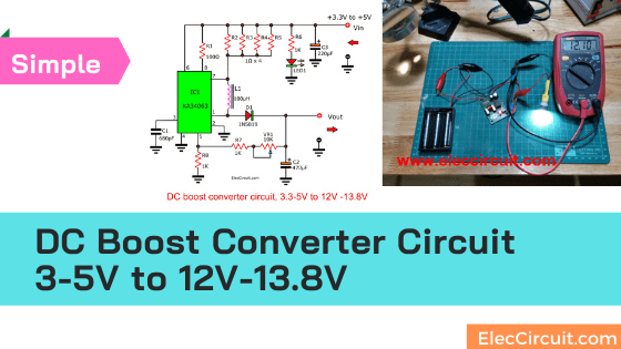
3.7V to 5V Boost/Step-up DC converter circuit using MC34063
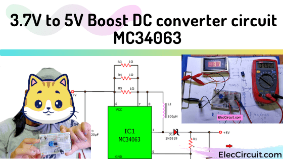
Here is a 3.7V to 5V boost converter or step-up switching circuit using MC34063 and a few parts,1N5819,100uH. For 200mA-300mA of load current.
Also 12V switch mode power supply
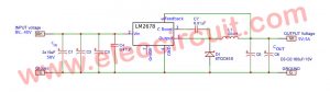
- LM2577 5V to 12V DC Converter step up Voltage Regulator
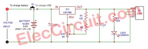
- LM2575 Switching Regulator 1.2-12V for Solar
- 12V to 16V DC/DC Converter with LM2577
What’s more? You can look other power supply circuits: Click Here

Related Posts

I love electronics. I have been learning about them through creating simple electronic circuits or small projects. And now I am also having my children do the same. Nevertheless, I hope you found the experiences we shared on this site useful and fulfilling.
Hi
I want to ask about the base resistor of the external npn switch, why there isn’t a resistor right there to limit the base current?
please provide a board view, why does nobody provide board views or gerbers anymore