This is an automatic water pump controller circuit project. Water is a valuable resource. There is water in us up to 70%. We need water Otherwise, we die.
We usually keep water in the so high tank. Then, let the water below through the water pipe.
Sometimes, No water in Tank. It needs to pump water into the tank.
It’s not comfortable. If you have to wait for a full tank. Then shut off the pump. Do not worry! This automatic water level controller circuit may help you.
Why make automatic pump control?
It will make you more comfortable Because it enables open – close water pump automatically. When full of water, was ordered off the water. But When levels gradually reduced To the required, Then turned on fully the water. So We do not have to worry about overflow and water out anymore.
We have 2 circuits. First, using a transistor version. Second, using the famous 555 timer.
Learn more below!
Using transistors version
The working principle
As Figure 1 shows automatic on-off switch for water pump circuit diagram.
In begin states when without water on a bucket. Both transistor Q1 and Q2 will not works.
Because the base of both transistors not triggered from the common point. Which still connect positive voltage through R1.
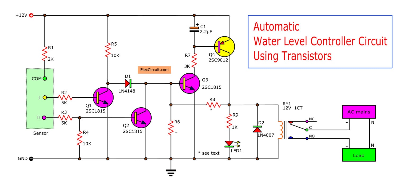
Figure 1 Simple automatic water level controller circuit
And this result to both transistors no conduction. So current through R5 and D1 to trigger base of Q3, cause Q3 conducts current to cause the transistor Q4 also works.
When Q4 conducts current, LED1 will get a forward biased. So it glows. And relay-RY1 will pull in to contact continuously a water pump with the AC-line 220 volts.
Until water to low level (L). So it work as conductor of electricity to base of Q1. To get bias and conduct current at collector. So there is voltage like ground.
But Q3 and Q4 exist voltage at collector. So there are voltage same the positive supply.
The current will flows through D1 to trigger base of transistor-Q3. So begin cycle working new again.
Recommended: How does an SCR work
How makes it
Because this project is small and uses less equipment so easy to build you can assemble them on universal PCB.
Or will make the PCB as Figure 2 (I am sorry for no copper layout).
You need to put all parts in the correct position, and matches terminal according to Figure 3.
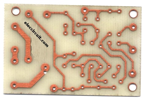
Figure 2 The PCB
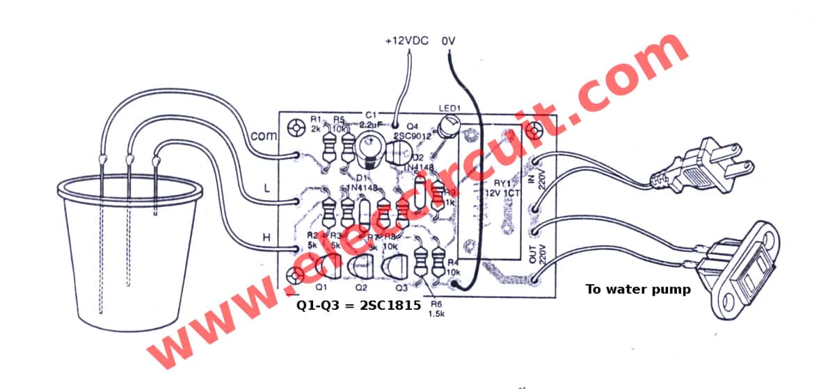
Figure 3 The components layout.
The external wires should larger size In particular 220 volts to load power should withstand a minimum of 600 watts.
The external 12V power supply adapter can be used from anywhere but must be able to supply up to 300mA.
In real deployment must bring them to mount in the box neatly and securely. Because the circuit is the voltage AC 220 volts in the PCB which will be harm easily.
Put it in a box must be steel or plastic. But must be durable.
Testing
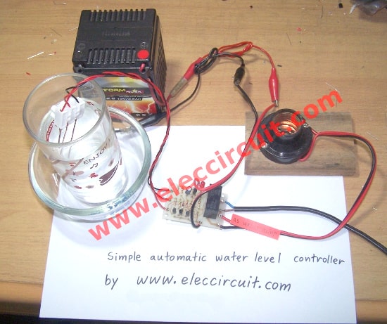
Figure 4 completely this project ready to test.
Remember, in the testing circuit, do not connect input and output to AC220V to this project, because maybe the danger while testing them.
Just connected DC 12 volts as a power supply to positive or +12V point and negative to 0V point. If not constitute any part of an error, the result follows.
Read next: Food & Water Salinity Tester Meter circuit
Firstly, when applying a 12V power supply into the circuit. The LED1 will glow and the relay will work. Then when we connect the “H” and “COM” point together.
Next, the LED1 will go out and the relay will stop working take “H” point out of “COM” point so cause LED1 will glow and relay pull in again.
Secondly, the short “L” and “COM” terminal, LED1 will glow and relay still working.
Then short “H” to “COM” another one point.
Now all three terminals are connected to each end.
As a result, the relay stops working and LED1 goes off.
When removing the terminal “H” out now relay will not function and LED1 will not glow.
When removable terminal “L” out of the terminal “COM” now relay with LED1 light up.
As video below, I am testing this project.
The Parts list
Q1-Q3: 2SC1815 or 2SC1740—NPN transistors or similar
Q4: CS9012—PNP transistor or similar
D1,D2: 1N4148—200V 0.15A Diodes
LED1: As you like
0.25W resistors
R1: 2K
R2, R3: 5K
R4, R5, R8: 10K
R6: 1.5K
R7: 3K
R9: 1K
C1: 2.2uF 25V—Electrolytic
RY1: 12V-1C 3A current relay
Wires, PCB, and others.
Application
Take three lines to connected to “L” “H” and “COM” terminal will be a general copper wire and cut them as the level you need but do not short-circuit. We may install it in the pond or water tank.
Note: Do not use a point detector in oil or hazardous chemicals. Because it may be a spark of the wire may cause the explosion.
Automatic Pump controller using 555 timer
This is an Automatic water pump controller circuit diagram using an NE555 timer.
In the countryside, water is very important. The most to use the groundwater to dig as a pond, and for the convenience.
They often use the pump automatically. But waste a lot of electricity.
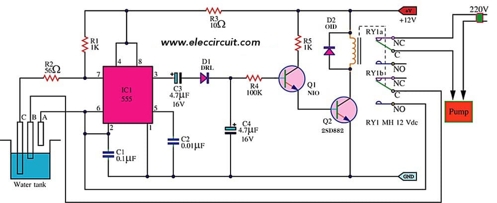
Automatic water pump controller circuit diagram
Some homes have a large water tank on high, then Pumping up the put on hold. When you want to use, just to turn on the tap at the bottom.
It does not require all-time electricity and also high water pressure.
Water tank system. Convenient and savings, but …
But I have to control the water level in the tank is fixed, is water must not out or overflow, which is a waste of time look at the pump.
I have the ideal to create this automatic water pump controller project.
Main ideas
When the water a full tank. This circuit controls the pump stopped working. Then we use the water out. The pump will start running again. This manner is ever automatically
Roughly description
The IC1 No. 555 works in the astable multivibrators. For signal generators to activate the transistor, which is used to drive relays – off the pump.
Assuming flood level to the test point C. (Will has flooded all the time.) But the water level has not reached the test point B. These parts to be IC1, Q1, Q2 (2SD882) and RY1 will not work. So the contacts of RY1a and RY1b be connected to the terminal NC, the 220 volt AC electricity can be supplied to the pump. The waters pump start to pump water into the tank.
Circuit parts
Q1: BC547, 45V 100mA NPN Transistor
Q2: 2SD882, 30V 3A NPN Transistor
D1: 1N4148,75V 150mA Diodes
D1-D5: 1N4007, Diode
RY1: Relay 2 contracts 12V
0.25W 5% Resistor
R1, R5: 1K
R2: 56 ohms
R3: 10 ohms
R4: 100K
Capacitors
C1: 0.1uF 63V Polyester
C2: 0.01uF 63V Polyester
C3,C4: 4.7uF 25V Electrolytic
Until the water level increases to the sensor point A, As a result, the sensor point A is connected to the test point C. The IC1 works and pulse signal generator.
Then through diodes, D1 and C4 both to be the DC voltage to the bias current to Q1, After the Q1 and Q2 (2SD882) conducts current.
As a result, current flows through the coil of RY1. So the two sets of the contacts (RY1) move on the poles NO, the pump will stop working.
The contacts of the RY1b sets will connect both test point A – B together. Although the water level drops below the test point A, the pump still does not work.
Until water levels drop below the detector B. Water pumps, therefore, started again. Which will circle as continue?
Check out these related articles, too:
- Simple high water level alarm circuit project
- Soil moisture detector circuits and automatic controller
- Simple solar plant watering alarm

Related Posts


I love electronics. I have been learning about them through creating simple electronic circuits or small projects. And now I am also having my children do the same. Nevertheless, I hope you found the experiences we shared on this site useful and fulfilling.
#Automatic water tank using pump controller by 2SD882
sir iam doing this as my mini project …will u plzz send me the detailed explanation including of each components and working and with a proper design to [email protected]
#Automatic water tank using pump controller by 2SD882
plz reply to me soon sir …….
#Automatic water tank using pump controller by 2SD882
sir do you have any videos/pictures about how it works? sir if you have plzz send it to my email:[email protected]
#Automatic water tank using pump controller by 2SD882
Want water tank control system 9810054905 in Pitampura,delhi pl send dealer add,ph no
#Automatic water tank using pump controller by 2SD882
sir iam doing this as my project …will u plzz
send me the detailed explanation including of
each components and working and with a proper
design and cost detail also to [email protected]
Qual d distancia macima que os sensores comandam no cistema ?
obrigado , muito bom o progeto.
can you pl explain how R1 to R 9 are calculated
plz sir, can you give the function of the components used on a circuit
What would be the maimun distance from electrode control to the controller? (Max. distance from tank to electronic circuit)
Really have you test this circuit? I am not sure it works due to D1 is supplying continuously current to base of Q3. If Q3 start Q4 conduction, it means Q3 receive feedback from Q4. Or, Q3 get the polarization circuit of Q4?
Hi,Neybero
Thanks for your feedback.
I really test this projects it worked as video above.
Thanks momename for your confirmation. Have you calculate the maximum distance between tank electrode and electronic circuit?. I am living in a first building level and the tank is avobe roof. Can it works?
Hi,Neybero
I use normal water in outdoor pool.
It’s sound good ” first project of you” .
It can work but you should test it on breadboard.
and slowly assemble them.
before my family don’t like Electronic, but now everyone demanding me, create a project every day.
Thaks momename, right now I am using two level switches and one relay to control the pump to fill up a tank. My question was in case a level switch got a problem I could change the control building the circuit of your design.
Hi, Neybero
I am sorry I don’t clear. About this next week I will take this project Make another one, upon the request of the wife.
Thanks.
I mean I am using level switch and a relay to control the pump. One of the level switches is having problem, may be I use your design to build.
#Automatic water tank using pump controller by 2SD882
Sir need detail explanation on this circuit.
I also need a 3kw D.C-A.C inverter circuit diagram
#Automatic water tank using pump controller by 2SD882
sir iam doing this as my mini project …will u plz send me the detailed explanation including of each components and working and with a proper design to my mail [email protected] project is auto matic water level control
sir, we are going to build this circuit using simple components. can we get the detail information about this project? details in sense how to build this circuit? components required for it? actually it is our college project for std 12th? can we get some guidelines for this?
#Automatic water tank using pump controller by 2SD882
Sir,
Can I use 2 relays in this circuit.
I can’t found 2 contracts relay in the market.
Plez reply soon
#Automatic water tank using pump controller by 2SD882
Hi, Suman
Thanks for your feedback.
You can use two relays to connect each coil in parallel. But this way current of coil is double.
Or use this Simple automatic water level controller circuit :https://www.eleccircuit.com/simple-automatic-water-level-controller-circuit/
Hi Neybero,
Thanks for your feedback.
I am happy you project works.
Hi aishwarya,
Thanks for your feedback.
I cannot show you PCB layout. but this project work as video.
Hi fahmi setiadi,
Thanks for your question.
Please with water and use circuit as Figure 3.
Three terminal level as show.
You can use Resistors as you have.
Hai sir , how many distance bet win tank to our controller I want to work min 200metars wat to do plz send mail thanks u sir
SIR, i need some pcb of autometic water levelcontroller can i purchase it from you? pl reply, bn ghosh.
SIR,i need some waterlevel controller circuit, can i purchase from you / pl reply. B N GHOSH
SIR am.doing my final year project with this.need waterlevel
controller circuit, can i purchase from you
I need to Manufacture fully automatic water level controller in India please give me details of project
#Automatic water tank using pump controller by 2SD882
Dear sir it is very useful circuit and after assambleing I am using this at my home
Thanks
#Automatic water tank using pump controller by 2SD882
hi
what is the coil resistance of relay @ 12v?
#Automatic water tank using pump controller by 2SD882
Sir
Am sorry my project somehow relating with this involving control the distribution of water at a university. please can you help to design a particular circuit
Hi Momename,
The Circuit is powering ON but when I shot LOW Common and HI Common its not powering OFF. The Circuit is always on. Please let me know what could be wrong.
Regards,
Jagadish
Hello sir can we use 220vac 1/2hp motor for this project
i cant find 2sc9012 in orcad so kindly give me the alternate one
Hi asif,
Yes, you can the relay can use for 3A-5A load.
Hi abid,
Thanks for visits, please find for 9012 transistor or use BC547 but different legs.
sir please explain this circut
#Automatic water tank using pump controller by 2SD882
sir, I am planing to fix some controller in my house for sump and over head tank. kindly help me in regard.I gone through your water level controler kit. Wher in it is having single tank feature.
#Automatic water tank using pump controller by 2SD882
Hello, me not understand about rely connection. can u describe please. thanks
Can I get these readymade from market pl
I suggest every one who wants duild this project to use inoxidable steel bars for better result. Cupper can oxidate and get low electrical conduction. It may be be momename has made testing with different materials. Am I wrong momename using inoxidable materials?
Distance is not a problem with its function. Any one can use a trhee cables conductor. Potential, neutral and a return one from relay contact to receptacle, using the neutral common with controller and pump. For 220v cable most be 5 conductor number. Relay of tow or three contacts.
With this option you can install the controller as near as posible from tank.
Sir. I am undergoing project on WATER LEVEL DETECTOR AND AUTO SWITCH. Pls i need ur help.
Hi Arafat, what do you exactily need? Can you give us more detail?
I’ve been surfing on-line more than 3 hours as of late, but I never found
any attention-grabbing article like yours. It
is pretty worth sufficient for me. In my
opinion, if all site owners and bloggers made good content material as you probably did, the
internet shall be a lot more helpful than ever before.
#Automatic water tank using pump controller by 2SD882
Sir help me in relay area.i dont understand how to connect them.
#Automatic water tank using pump controller by 2SD882
Sir, please you can help to practical circuit
Hi admin ,
i am fresher and just join a comapany and they give project to connect a water pump to a SS water tank in such a way that when tank is full then automatic 2hp motor will shut down and when it water reach to lowest point then automatically start. Please guide me.Please provide me the circuit diagram with pcb circuit .along with it part and function.
My email id [email protected]
Hello . Could you help me? You need a scheme to only indicate the level without pump.
I am in process to develop a device for automatic water pump controller with float sencer.
Can you please share the cercuit diagram with components details.
Regards,
Asish Ray Chaudhuri
it’s automatically working one or two week, then it’s copper probe has been damage
Hello!
I’m trying to build this circuit but it’s not working, may you please provide me with an alternative circuit because I have to use it by tomorrow morning in my presentation.
Thanks
Hi, Mabula N.I
Oh…I am sorry to hear that. I assure you it definitely works. Please check your soldering. And electronics components again.
Hello sir am writing from Nigeria. . Have simulated this circuit Using circuit wizard and I works… How ever I replaced the transistors with a general purpose NPN BC548 and PNN 577 respectively. Please what is the function of the capacitor and can I add multiple levels to indicate the different water levels without any damage?
Thanks.
good project
Hi MR OHM 1970
Thanks for your feedback.
Hi i need ur help to single level circuit. Once tank level is high motor need to stop.
Hi Ushman,
Thanks for your question.
I am happy to help you. I am not sure can you, or not.
There is circuit,Simple high water level alarm circuit
https://www.eleccircuit.com/simple-high-level-water-alarm/
You may use the 9V relay instead of the Buzzer.