Let’s experiment with TL431 circuit instead of the Zener Diode regulator. Have you used Zener Diode before? This IC works in the same way, but with more efficient, easy to use, and inexpensive. So, we often find it in a variety of common circuits.
TL341 datasheet in short
Before using anything we should learn its basics first, the TL431 is no exception.
What is TL431 shunt regulator?
It is a three-terminal programmable precision shunt regulator IC
The TL431A has a programmable Vref(Reference voltage) from 2.5V to 36 V with only two external resistors. These components adjust a wide operating current range of 1.0mA to 100 mA with a typical dynamic impedance of 0.22 Ohms.
It is specified thermal stability over applicable temperature, Reference Input Voltage 2.520V, Output Voltage to 40V, and Tolerance of 1%.
When Vref gets a voltage of 2.5V up, its output circuit gives a sharp turn-on form, causing it to be a great pick instead of Zener diodes in a lot of usages.
TL431 FEATURES
- Programmable Output Voltage to 40V
- Guaranteed 0.5% Reference Voltage Tolerance
- Low (0.2Ω Typ.) Dynamic Output Impedance
- Cathode Current Range(Continuous) – 100 ~ 150 mA
- Equivalent Full Range Temperature Coefficient of
- 50PPM/°C
- Temperature Compensated For Operation Over
- Full Rated Operating Temperature Range
- Low Output Noise Voltage
- Fast Turn-on Response
- TO-92, SOT-89 or SOT-23 3L Package
What can it be used for?
- Shunt Regulator
- Precision High-Current Series Regulator
- High-Current Shunt Regulator
- Crowbar Circuit
- PWM Converter With Reference
- Voltage Monitor
- Precision Current Limiter
Learn others datasheet HERE
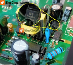
We often found TL431 in switching power supplies, battery chargers, voltage digital, etc. In this experiment, we take it from a digital TV set-top box, in the section of the 5V power supply. Fortunately, TL431 still works.
TL431 pinout
Let’s look at the shape of the TO-92 packet. With the ease of use by having a similar shape to a 2N3904 transistor, looks at the TL431 pinout below.
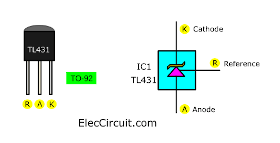
When we look at the front and leads of TL431:
- The center is Anode, it is represented with the letter A.
- On the left is Reference, it is represented with the letter R
- The right is Cathode, it is represented with the letter K.
Next, we will call it in short forms R, K, and A.
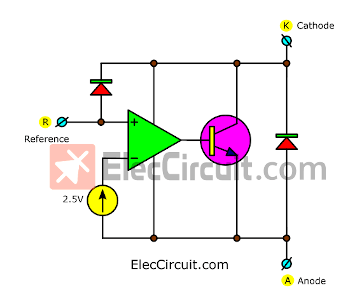
Then, look at Simplified Block Diagram. It looks like has many components inside TL431, including comparator Op-amp, reference voltage, transistors, and more. So, it has higher efficiency than the Zener diode surely.
Experiment with TL431 circuit
We believe Learning through experiments causes more understanding.
We can use it as a linear regulator in many ways such as:
How TL431 works as a fixed Zener diode regulator
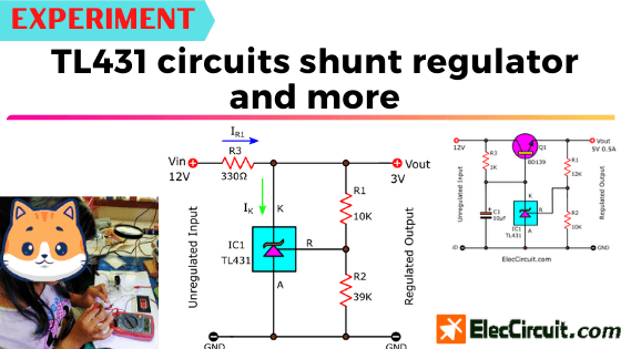
First, try the basic shunt voltage regulator circuit. See in the circuit.
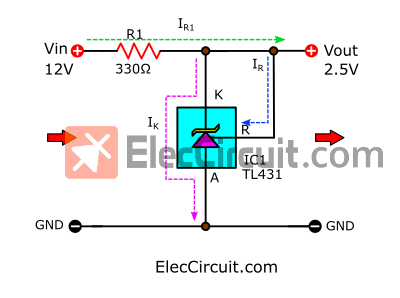
It looks like the Zener Diode regulator, the R is connected to K.
It has more temperature stable than a Zener diode. We should pick R1 resistor values to limit Ik to between 20mA and 40mA.
The electrical current flows through R1 and IC1 to the ground. The TL431 will keep a fixed voltage at 2.5V across it.
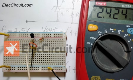
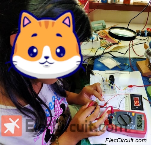
My daughter measures the output voltage(Vout) of about 2.5V as a principle above. So, the reference voltage is 2.5V.
The output current is almost IR1(current through R1). Because IK (current through IC) is very tiny.
We can find IR1 or Iout easily.
IR1 = (Vin – Vout) / R1
IR1 = (12V – 2.5V) / 330Ω
= 0.0287A
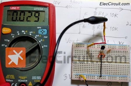
We experiment to measure that current with the digital ammeter, it shows 0.029A, matching the principle.
Variable voltage Zener regulator mode
If we want a 3V output, we use a voltage divider with R1 and R2, to compare the voltage between the reference and output.
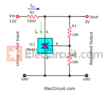
We can find the output voltage from:
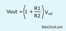
Vout = (1 + R1/R2) * Vref
= {1+(10K/39K)} * 2.5V
= 3.141 V
Set output voltage TL431 with divider resistor R1 and R2
But we measure an output voltage is 3.06V. It is worked.
5V shunt regulator using TL431
Also, if we want 5V output. We change R1 and R2 are 10K. See the circuit below.
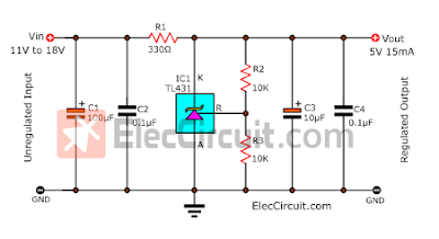
The output voltage is 5V. The output current depends on the Vin. The Vin is from 11V to 18V. Such as Vin is 12V, Iout = (Vin – VK) R1
= (12-5V) * 330 = 21mA. If Vin is 18V, Iout will increase to 39mA.
If we want the other voltages, can change R2 and R3 as the formula above. The C1, C2, and C3 are used to filter the DC voltage and keep low noise and low ripple.
Adjustable Regulator circuit using TL431
For some levels of output voltage, we hardly find proper values for R1 and R2. So, we should use a potentiometer to help.
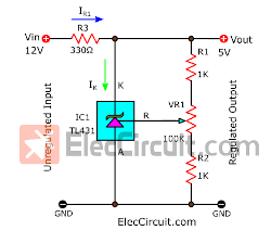
In the circuit below, we use a 100K potentiometer to adjust a reference voltage. If you want a 5V output then adjust VR1 to about center. So, this IC is better than a Zener diode for stable variable reference voltage.
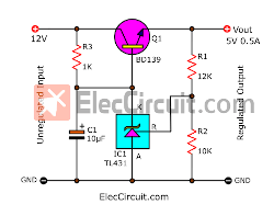
Series regulator passing transistor
Usually, TL431 will only deliver a current under 100mA. but if we need a higher current, such as 500mA, 1A, 3A, etc. We can use a series pass transistor to increase a current, by doing this will convert our shunt regulator into a series regulator.
In the circuit below, the output voltage is 5V at about 0.5A.
Now, let’s calculate the simple value of the components.
Q1:
We choose BD139, 1.5A 80V NPN transistor. It can drive current for this case. Its hFE gain rate is 100 min.
Due to the voltage loss at B-E of the Q1-transistor of about 0.6V. The voltage at B (VB) of the transistor must be offset to about 0.6V.
For example, if the output is 5V the voltage at B should be 5.6V.
R3:
The current flowing through R3 is the base current (IB) of Q1.
Since the current flowing through K-A of IC1 is quite very low. We so consider only IB.
But IB should be not over 40mA.
IB = IC/hFE
We know IC = Iout = 0.5A, hFE = 100
So, IB = 0.5A / 100
= 5mA
R3 = (Vin-VB)/IB
We know Vin = 12V, VB = 5.6V, IB = 5mA
So, R3 = (12V-5.6V)/5mA
= 1.28K
But we pick a 1K resistor instead. So, the IB current increased to about 7mA
R1, R2
We pick resistors R1= 12K and R2 = 10K. Then, we calculate to find the output voltage.
Vout = 1+ (R1/R2) * Vref
From: R1, R2 = 10K, Vref = 2.5V
So, Vout = 1 + (12K/10K) * 2.5V
Vout = 5.5V
Then, test this circuit on the breadboard, and measure the voltage, it is about 5V. Then connect 10 ohm 10W resistor as load, measure its current, it should use current about 0.5A.
Check out this Breadboard. I think it is interesting maybe it is right for you.
If you want a 1A output current. You may change R3 to be a lower resistance, such as 470Ω, 330Ω, etc. But should not be lower than 330Ω or the current flow through TL431 will be too high.
If you want more than 1A but must be within the 2A range. You may change Q1-transistor to TIP41 or 2N3055.
But if you need more than 3A current you may the Darlington transistor instead.
We would love to show you how it worked in full detail, but it has to be next time.
2.5V voltage detector circuit using TL431
Test if it is dead or not
We have pulled this IC from an old circuit board. But we are not sure if it still working or not. It can not be tested with a regular meter. But we can use it to create the simplest circuit to determine if it will work.
This “simplest circuit” is the 2.5V voltage detector circuit.
Its main principle only consisted of voltage at R exceeding 2.5V triggering the current to flow from K to A of this IC, which is similar to how the normal Zener diode works.
Let’s try to create this circuit.
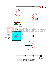
The current flows through R1 and VR1 to the ground, they are the voltage divider circuits. We measure the voltage across R and ground.
At first, the VR1 is set to lowest, meaning the voltage is also the lowest. At the same time, the LED goes out.
Then, we adjust the VR1, the voltage is higher to 2.5V. The current can flow through K to A, causing the LED1 to glow.
The R2 is a limiting current for LED1.
There is a simpler version than this.
The Logic voltage detector circuit
This circuit is used to detect logic in a digital circuit with a few components, only consisting of 2 parts. It requires a 5V power supply.
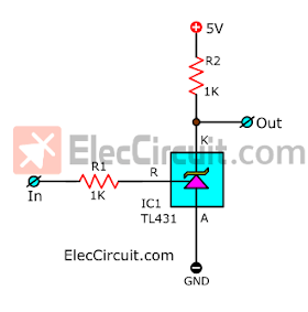
When the input logic is “Low”, it makes the output 5V.
On the other hand, if the input logic is “High”, it makes the output 1.8V.
Thanks for the good information:
- TL431 Voltage regulator IC read more in technical terms.
- Experiments with TL431A Shunt Regulator. Read more
Conclusion
From all of our experimentation above, we found out that the TL431 has high efficiency. We have planned to integrate it into other types of circuits/mini-projects, like battery chargers, timers, switching mode power supplies, or even more. If we finished thoroughly testing it, we will notify you via email, so please stay tuned.
Download This Post
All full-size images and PDFs of this post are in this Ebook below. Please support me. 🙂


Related Posts


I love electronics. I have been learning about them through creating simple electronic circuits or small projects. And now I am also having my children do the same. Nevertheless, I hope you found the experiences we shared on this site useful and fulfilling.
Thank you very much for this wonderful work, and I want to warn you that there is an error in the expression “output voltage” when used as variable voltage Zener regulator mode:
Vout =(1+R1/R2)×Vref.
Hello BOUZIDI Riad,
Thanks very much. I have successfully updated it.
You are awesome. My daughter joins in learning math. Electronic work is related to a considerable amount of mathematics.
Have a nice day
Thank you
I do have a few TL431s that I have harvested from some old equipment. I can try out your projects
I used to go to rummage sales and buy old TV sets, computer monitors and etc., and enjoy pulling them apart. I built up my stock of components that way. There were a few TL431s that I got that way.
Nowadays, the used or defective electronics all jave panels with SMD components whivh, at my age, I cannot bother with.
You are doing such an amazing job, keep it up. Good luck to you and your family. You are extremely lucky to have kids who share your interests. Thank God for them.
Best regards
Ivor
Excelente
Thanks, I appreciate you for this.
So the Tl431 is like a programmable zener. Diode..I love it!!! So if you need a precision output voltage this is the guy to choose!! Great theory ad usual…Thanks!!!
Hey my friend,
Thanks for your feedback. I am happy that you like it.
Merci beaucoup pour des explications.
Cordialement
avec grand plaisir (with great pleasure)
Your work is fantastic a great contribution to people being able to learn with little expense and such a clear explanation almost unique and teaching the young useful skills for their future. Keep going you are doing brilliantly.
If I have a query it is if the shunt regulator wastes unwanted energy the bypass just bleeds off that what is needed barring control power 20 percent or so.
Is that correct ?
Hello, my dear friend,
Your text makes me so happy. It makes power for us (me and the kids). We will keep this electronic learning up.
We need income to buy tools and electronic components to continuously create electronic work. Thank you for your kind understanding.
Yes, you are correct. I often use TL431 as a voltage detector circuit, in switching power supply, etc.
God bless you always are happy.
It is always a learning experience!!!!!Thank You once again!!!
Hi, my dear friend,
How are you?
Thanks! It is good to read your text. It makes power for us (me and the kids).
We also always learn electronics the same you.
God bless you always are happy.
I am great as long as you continue doing this!! I took Electronic Engineering 46 years ago and find this forum a a relearning and refresher experience!! keep up the GREAT WORK!! Thank You. MROHM1970
Hi, dear friend,
Thanks for the feedback, I appreciate your very valuable experience. Some techniques or electronic circuits are never outdated, very good to learn. I am very glad that you still don’t forget it. My kids and I will continue to learn these circuits as long as we have the components.
God bless you.
RECEBI A INFORMAÇÃO
You are welcome!
Hey friend, you are missing a slash in the expression “IR1 = (12V – 2.5V) 330Ω”, in the first example.
Thanks, my dear friend.
Oh. Sorry for the incorrect.
I just corrected it.
Good day,