This circuit is built to add to the capacitance measurement range for a general digital multimeter which is small,cheap and most popular.
Normally it cannot indicate the exact capacitance. If add an only slightly circuit. and Used in conjunction with the digital multimeter. I can know the exact capacitances.
How it works
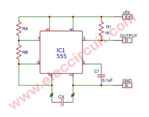
The circuit in Figure 1 is increasing the capacitance measurement range for a general digital multimeter. By have IC1/1 as the oscillator circuits work together with the potentiometer-VR1 and fixed capacitor-C1, C2, C3 or C4 by have the selector switch -S1 the frequency of the oscillator. by the determined value of VR1 and capacitance that one of the values. The output frequency through a buffer-IC1/2. Some current will go directly to an input of IC1/4.
But another some part is through the inverter-IC1 / 3 and signal will have the time delay which It depends on the capacitance to be measured or the Cx.
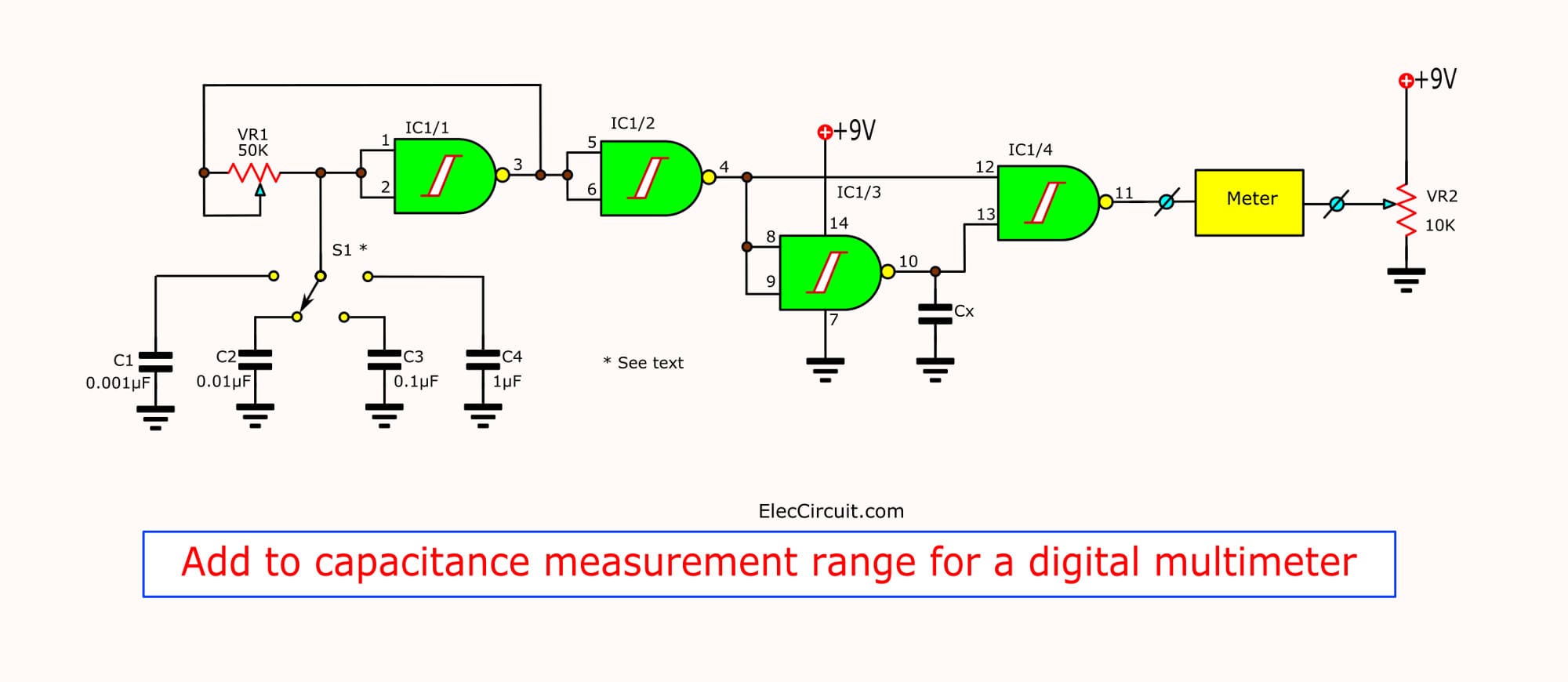
Figure 1 the circuit add to capacitance measurement range for a general digital multimeter.
By normal if not have the Cx value , the signal output from IC1/4 will show states “high” and “low” The duration or width of the pulse in “low” channel Will effect of capacitance to be measured. or Cx value. Thus The ratio of the period between the “high” and “low”. So is setting the capacitance and display as average voltage from digital voltmeter.
The measurement a capacitor. In no event Cx. set range in range 2 volts, adjust a variable resistors(potentiometer) VR2 to read at 0 volts per Cx value or measure a capacitors set frequency. By selects at a switch-S1 and adjust VR1 to measure capacitance correctly. The circuit can use to measure the low capacitance between a few picofarad up to many microfarad the value that is read from the digital voltmeter will display is voltage,can read with select the switch-S1 at either capacitors Then use that value to multiply the reading. And will be capacitance at can measure them such as read 0.5 volts at select-S1 at 0.001 uF thus the capacitance equal 0.5 x 0.001 will is 0.0005 uF or 500 pF.
How to build
This project is not used many components so can assemble on the universal PCB board as Figure 2
In the assembly circuit, Starting equipment lowest first such as Diode and then resistors and sort of high continuously.
For the device has various polarity should be careful in the assembly circuit. Before placing these components will must set the polarity at PCB and the part match together because If you put backward, may cause equipment or circuit damage. How to check polarity and input device.
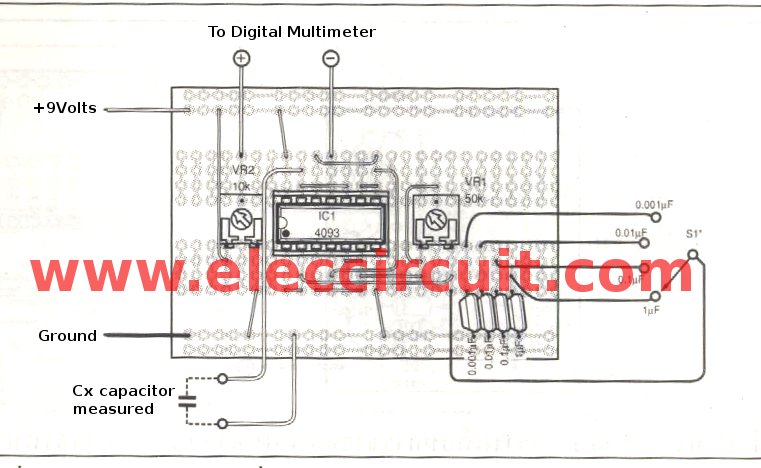
Figure 2 the components layout of this projects
The soldering iron is less than 40 watts. And Use of lead solder containing lead and tin in the ratio of 60/40. Including the need also to have a flux inside the lead.
The after that put the components and completely solder. to check correctness again But if you enter the wrong position. Should use a desoldering pump or a Desoldering remover To prevent damage to the PCB.
The components list.
Horseshoe-shaped standard potentiometers
VR1: 50K
VR2: 10K
The Polyester capacitors
C1: 0.001uF 50V
C2: 0.01uF 50V
C3: 0.1uF 50V
C4: 1uF 50V
The Semiconductor
IC1: CD4093 Quad 2 input Schmitt NAND Gate IC
Others
S1: the selector switches of 4 step
The universal PCB board.
Related Posts

I love electronics. I have been learning about them through creating simple electronic circuits or small projects. And now I am also having my children do the same. Nevertheless, I hope you found the experiences we shared on this site useful and fulfilling.
can i use analog voltmeter