If you are looking for an Acoustic-guitar-pickup circuit that cheap and you can build with yourself.
Suitable for the show enjoyment of the party at home or in a group of friends.
This project is a good answer. For people like to play surely acoustic guitar with no pickup in it.
Known piezo speaker
The piezo speaker mostly is used as the driver for the audio signals. Such as in a digital watch or a warning voice types.
As the structure of the piezo is crystal with special properties that can generate a voltage from the pressure of crystallization.
We can use it instead of the general microphone by By which it can respond to vibrations and high sensitivity.
When considering the structure of the acoustic guitar. Guitar body is wood and is designed to be hollow.
When players strum guitar strings which is designed to the size and tension of the lines are different. by patterns of the sound of music.
In science, When an object vibrates at any frequency. Would become a sound wave. That sound wave will travel through the structure of the wood body guitar.
When we put the piezo speaker set up on the structure of guitar body is made of piezo crystals have better string vibration of the guitar itself.
The piezo will generate a small voltage to which we can put to use in the future.
Recommended: Electric guitar FM transmitter circuit from Acoustic
The working of the circuit
As shown Figure 1 We start from the strum the guitar. Guitar string vibrates, causing sound to come out.
Body vibration on the acoustic guitar could be passed to the piezo. Resulting electrical signal out.
The electrical signals that are sent through the C1-capacitor into pin 3 of IC1.
Read next: LM3875 Gainclone Amplifier circuit | Stereo 56W
Which the op-amp IC serves to amplify the small signal to large increase by rate with a gain that is determined by the ratio between R5-resistor and R3-resistor.
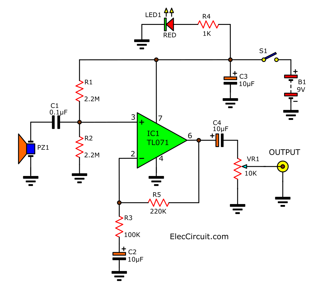
Figure 1
The gain of the circuit is 3.2 times. Then the signal through the expansion to a large.
Then be passed to the C4-capacitor, and through a potentiometer to adjust the volume before sending it to J1. Which is a jack for connecting the input signal to the amplifier is available.
Process of building
Because this project, have fewer parts. If you do not want to build a typical PCB. You can use as a Universal PCB Board.
Read also: Simple audio alarm circuit using transistors
By soldering and placement itself. Which can build in a short time. But need to check the wiring carefully.

Figure 2
But if you like tidiness so can build the copper-based model in Figure 2 as easy.
When done, it should check deficiency and short-circuit by copper. Inspection at all times. Will help prevent problems.
This does not work for this project.
The next step is to assemble various electronic components on the PCB, as in Figure 3.
Then, the wiring between the PCB and other devices such as The switch, volume, battery terminals, and output jacks.
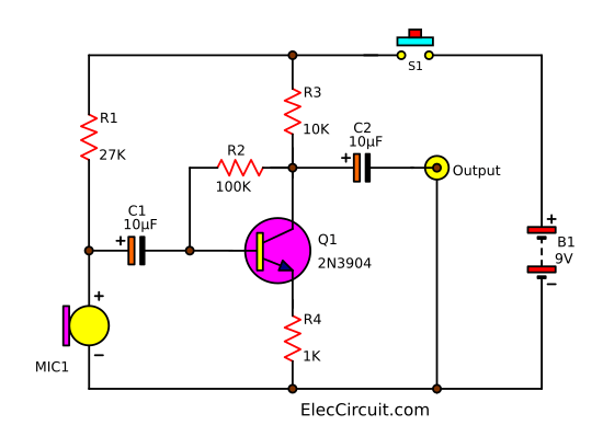
Figure 3
List of the parts
The resistor, 0.25W +-1%
R1, R2: 2.2M
R3: 100K
R4: 1K
R5: 220K
VR1: 10K (B) Potentiometer
The capacitors
C1: 0.1uF 63V Polyester Capacitor
C2, C3: 10uF 50V Electrolytic Capacitors
The semiconductor
IC1: TL071
LED1: LED size 5 mm
Other parts
B1: Battery 9V within Pole Or 9V power supply circuit
PZ1: Piezo speaker
S1: Switch ON/OFF
J1: Mono jack socket size 6.3mm
Etc.
Testing and implementation.
A very easy to use, just put the piezo plate attached to the guitar body. and the output has to enter into the guitar amplifier circuit. or other amplifiers that we use.
Adjustment of the volume to the minimum position before. Turn ON switch the power supply to this project will see LED1 glow light.
Then accelerated volume modest position.
Then the guitar’s sound output to the power amplifier is active or not?
When it came out, then adjust the volume to suit the actual use next.
For this project. Shown to have fun with friends. Various festive party. But it is not suitable for Showing or recording professional high quality.
Not only that see other ideas
Wireless Electric guitar circuit from Acoustic
This wireless acoustic guitar pickup circuit is used to Modify an Acoustic into the electric guitar on FM wireless transmitter system. It is small, cheap, easy to build. The acoustic guitar pickup of this circuit like working with the condenser microphone.
How it works
This is good because This system has less distortion than the general guitar pickup, which includes magnets and coils, which may be hard to find and expensive.
The 88 MHz FM transmitter circuit can be listened to with the standard FM radio. This frequency is determined by the value of L1 and capacitance between the plate-P1 and guitar strings that are connected to ground through a crimping terminal, the capacitance is about 5 pF.

Figure 1 the Electric guitar FM transmitter circuit diagram
When strum Guitar strings to make the capacitance changes. And we connect P1 to L1 as the frequency generator circuit will be FM modulation, send to broadcast transmission on the FM radio.
How to build
You should assemble the circuit into a small metal box that can tighten the nut mounted CRIMPING TERMINAL fit. And, a metal box with a ground circuit. Next, Connect the cable from P1 should be as short as possible. (See in Figure 2)

Figure 2 How to install the circuit on the guitar.
The parts you need
Q1: 2SC1815, 0.4A 40V NPN transistors
Ceramic capacitor
C1: 0.01uF 50V
C2: 0.005uF 50V
0.25W Resistors tolerance: 5%
R1: 100K
R2: 56K
R3: 1K
B1: 9V battery and snap connector
L1: Coil 5 turns of 28 AWG with a inside diameter of about 0.25 inch.
You make the plate from thin sheets of aluminum, wide and 1 cm, length 8 cm. Then, Place under the guitar strings is about 2 mm.
Adjustment and usage
First of all, adjust the frequency of the FM radio to 88 MHz. Second, stretch-shrink L1 while slowly play the guitar until hearing a sound on the radio. Then, close the lid for good. Next, tune the radio to hear a bit more clear as possible. Now, it can play.
If the building has problems “wave away”. You may cut thin metal cover plate over the guitar strings from P1 until carton circuit. Then, fastened to the box lid, to solve the wave crashes. Periodic spread spectrum of about 20 meters.
Here are a few related circuits you may find helpful, too:
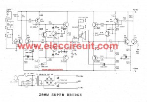
- Bass guitar super bridge amplifier 200 watts.
- Guitar preamp circuit – overdrive using 12AU7
- 3 circuits of guitar fuzz box and fader control
Related Posts


I love electronics. I have been learning about them through creating simple electronic circuits or small projects. And now I am also having my children do the same. Nevertheless, I hope you found the experiences we shared on this site useful and fulfilling.
Can you modify this with a standard equalizer or tone adjuster
Hi,Ronald Sta. Maria
Thanks for your feedback.
Yes, you can use.
you have equalizer and tone from ad? please send for me! Thanks!
Hello. Can I use mono jack size 3.5mm? Thank you a lot.
Hey!!! C1 : 0.1 uF 63v
C2,3 : 10uF 50v
C4???? I don’t know!!!
10Uf 50V
Looks just the job for me!!
Any tips on adding EQ…..Bass, Middle Treble controls please???
Thanks
Kev/Leeds/UK
if am using a bigger speaker, will i still use the same component values?
I made it and it’s working! But only when I plug earphones.. When I plug speakers with built in amp it doesn’t work.. It work but I can’t hear anything. Can you help me with this?
me too, connect with amplyfier it not work… sound noise and low….
i’ve just buid this one. I ok when connect PC, and laptop. But when i connect that with amplifier not working. The sound verry noise, and low. What problem when i connect with amplifier? Please help me!
what’s problem? why delete my comment AD?