These are 4 simple 50w OTL audio amplifier circuits using 2N3055 as main parts. We can build easy and cheap. It’s durable and very loud sound, Not needed speaker Protection. We use all transistors and LM3900 below.
50W integrated audio amplifier circuit using 2N3055
This is 60W RMS OTL integrated audio amplifier circuit using 2N3055 and normal transistor.
It is so cheap and can build easily. And, It’s durable and very loud sound for mini PA
From the previous project, some people say that Not suitable for a small party. Because of soft and does not durable.
So I highly recommend this project are The classic OTL integrated amplifier that power output 55 watts.
The its feature is loudly than other circuits and watts are equal. the speaker has durability and be difficulty damage.
And build easier OCL amplifier.
Although some people say that it is not good bass. But if you try, you may like it.
How it works
Look at a block diagram of this project.
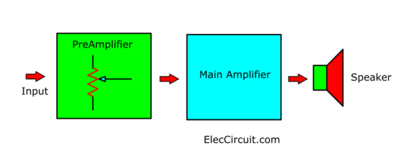
As show Figture fo this circuits.
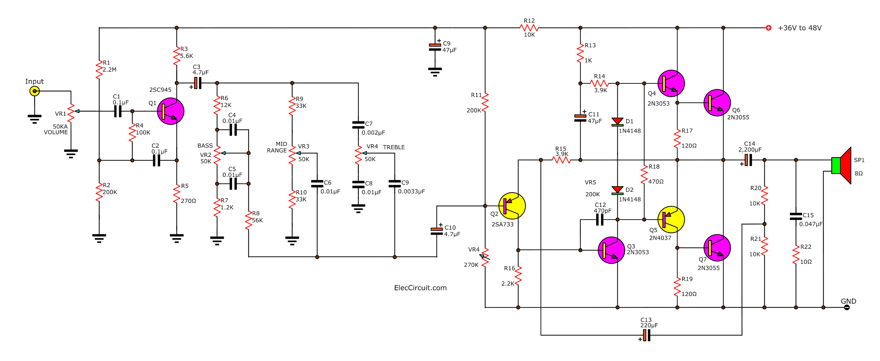
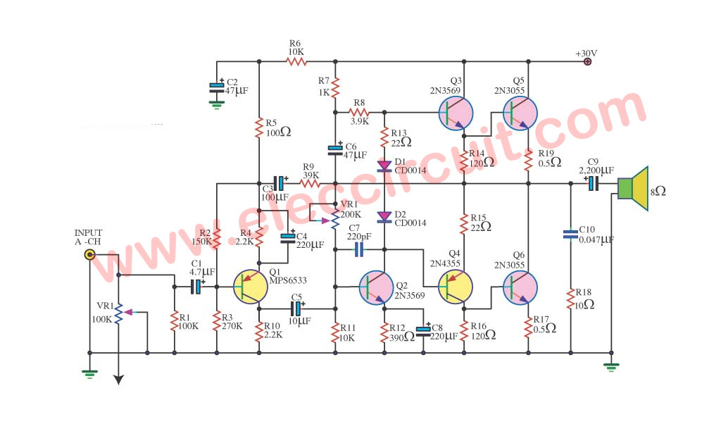
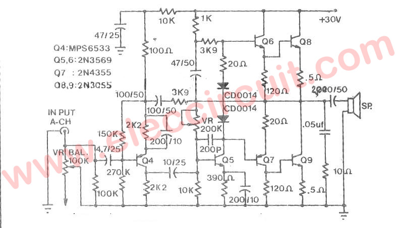
Figure 1 the complete circuits of circuit diagram.
They consists of two large parts are the main amplifier and tone control circuit Same as the previous circuit.
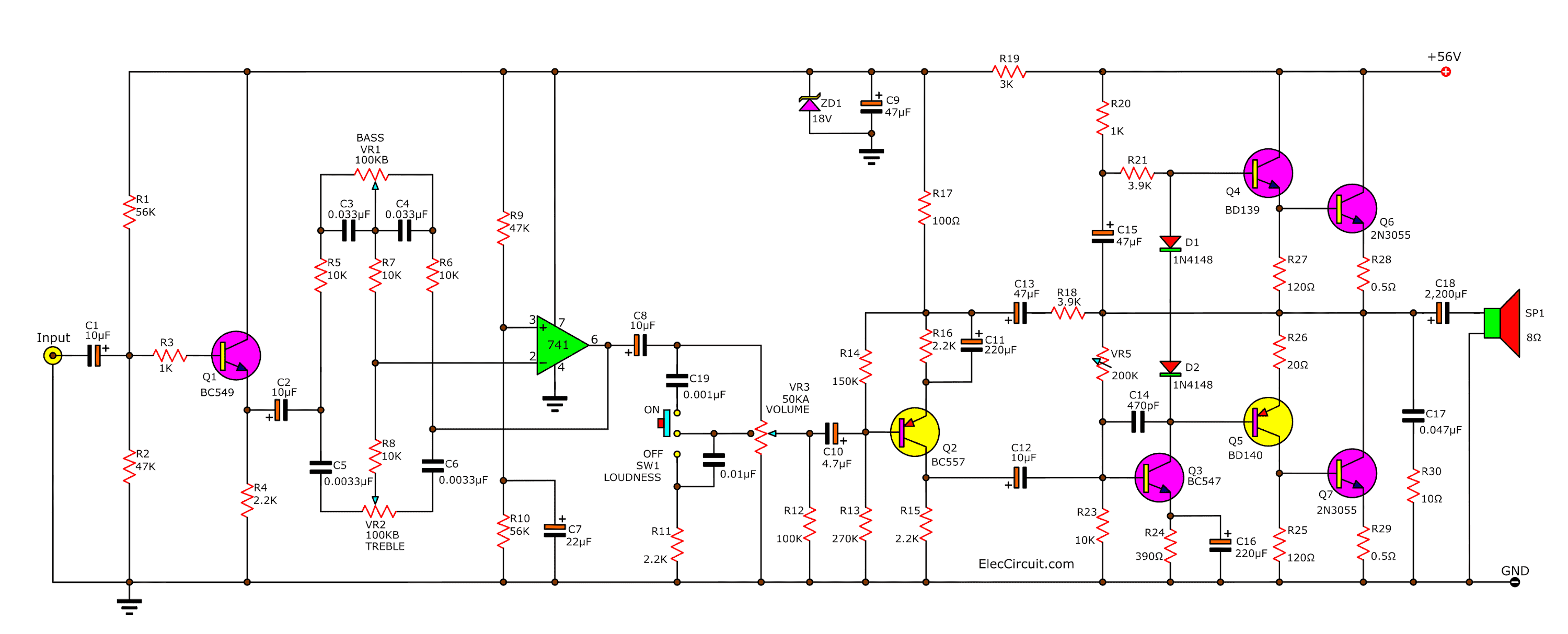
The tone control circuit consists of Q1-transistor and IC1( op-amp IC-LM741).
The signal input will enter to C1 and R3 into base of Q1. Which acts as matching between the input circuit and tone control-IC1.
VR1 is used to adjust the bass sound.
VR2 is used to adjust the treble sound.
Which this circuit can adjust the bass/treble to upper or lower up to 18 dB.
The output from the tone control will be entered through C8-capacitor to the level sound controller circuit is VR3-potentiometer and the loudness controller.
The signal from volume will enter through to base of transistor-Q2.
To amplifier the signal higher, that enter to pre driver Q3.
To drive the driver circuit with Q4, Q5 and the both power transistors Q6, Q7 next.
How to builds
Since the circuit is designed as well. So easy to create. However, to the best results. Should perform the following.
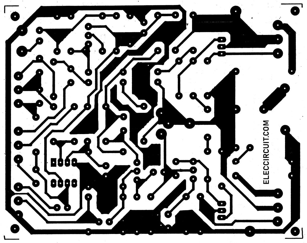
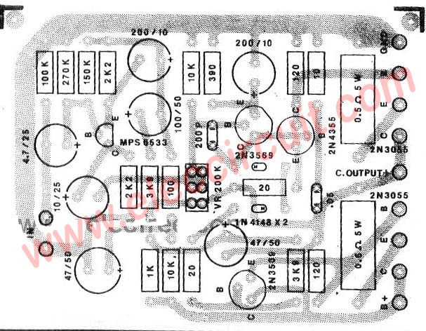
The Figure 2 Actual-size, single-sided PCB layout for the circuit.
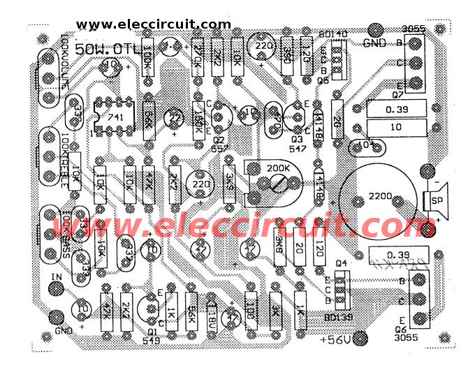
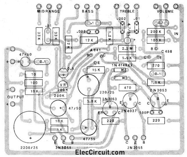
Figure 3 the Component layout for the PCB
1. Check the correct finished in putting all components.
2. Do not connect the power transistor.
3. Use the voltmeter measures at 2 points C17, C18 compare to ground.
4. connects the positive 56 volts to this circuit and then adjust VR4 until read meter about 28 volts.
5. connects properly the power transistors to the circuit
Also: 100w amplifier circuit with PCB
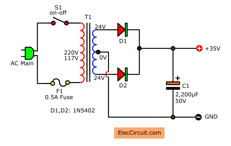
The power supply circuit
In the figure 4, The voltage 56V for this circuit. We are derived from the bridge rectifier to change from AC40V. to as DCV. then pass the filter capacitors , and then will obtained is the 56VDC.
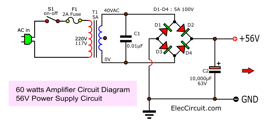
Figure 4 The power supply circuit
The transformer that use for the mono type, should use size is 2A and size under 3A in the stereo system.
Read next: 4 transistor audio amplifier circuit
The detail of parts list
IC1: LM741, General Purpose Op-Amp
Q1, Q3: BC548, 45V 100mA NPN Transistor
Q2: BC557, 45V 100mA PNP Transistor
Q4: BD139, 80A 1.5A PNP transistor.
Q5: BD140, 80V 1.5 PNP Transistor
Q6, Q7: 2N3055 100V, 15A, 115W, >2,5MHz NPN transistor
ZD1: 18V 0.5W Zener Diode
D1, D2: 1N4148, 75V 150mA Diodes
0.25W Resistors
R1, R10: 56K
R2, R9: 47K
R3, R20: 1K
R4, R11, R15, R16: 2.2K
R5, R6, R7, R8, R23: 10K
R12: 100K
R13: 270K
R14: 150K
R17: 100 ohms
R18, R21: 3.9K
R19: 3K
R20: 1K
R22, R26: 20 ohms
R24: 390 ohms
R25, R27: 120 ohms
R28, R29: 0.5 ohms 1W
R30: 10 ohms 1W
Potentiometers
VR1, VR2: 100KB
VR3: 50KA CT
VR4: 200K PRESET
Electrolytic Capacitors
C1, C2, C12: 10uF 16V
C7, C8: 22uF 16V
C9, C13, C15: 47uF 16V
C10: 4.7uF 16V
C11, C16: 220uF 16V
C18: 2,200uF 35V
Polyester Capacitor
C3, C4: 0.033uF
C5, C6: 0.0033uF
C14: 470pF
C17: 0.047uF
C19: 0.001uF
C20: 0.01uF
The detail parts of the power supply
T1: Transformer Secondary for 40 volts 3A-5A. ( for a stereo system)
D1-D4: Bridge diode >5A.200V
C1: 0.01uF 100V, Polyester Capacitor
C2: 10,000uF 63V, Electrolytic Capacitors
What is more?
Is it too high power? You want lower, right?
Try below.
30W OTL amplifier working using 2N3055
Friends may like old power amplifier circuits. Today I will show you the integrated OTL power amplifier circuit with PCB, 35W. Using 2N3055 is the main component.
How it works
It is an interesting circuit. Because of moderately sound 35 watts at the 8 ohms loudspeakers.
It is the OTL type, so it is easy to build, economize, and durable.
Besides it still has the full function to adjust the output sound. Such as Volume, Bass, Treble, Mid Range, etc.
Then, it is convenient for you, who is a novice want to build a power amplifier circuit.
Keep used by oneself and I have model PCB simply give friends.
The 36V power supply of 35 watts amplifier
PCB layout of 35 watts to 45 watts amplifier using 2N3055 transistor
This is a 36V to 50V Power supply circuit for 35 Watts to 50 watts amplifier circuit.
Get convenient in building with Have a good time. With the sound of music.
Selecting and substituting components
These circuits are highly flexible. I believe that he has good electronic skills. But I want to review him about the transistor substitution number.
And pinouts of different transistors. Look at below.
The Small transistor. Look at Their Pinout of TO-92:
- 2SC458, 2SC945, 2SC1815 and more.
- BC547, BC557
Power transistor 2N3055. Look at the pinout of the TO-3 transistor.
Use TIP3055(TO-3P). We easily install it on the heatsink.
Look at TO-39 and TO-225 transistors.
Sometimes we can use 2N3053 instead of BD139. And, 2N4037 instead of BD140.
50W Main audio Amplifier circuit OTL using 2N3055
If you are seeking power Amplifier at the loud good sound, durable and economize. We recommend the 50 watt audio amplifier circuit using 2N3055. Because, it use the equipment that seek good easy and build not difficult with. Many you who tell amp OTL the sound is not good. Me chest edge that be not the loud sound is excellent.
Then like to use general ( in the past ) although in contain divide still have use. I like it fining decorates the circuit.
Just you feed power supply 50V 2A also the work has already and a loudspeaker should use 8ohm 12 inc. sizes. Besides still model PCB for the convenience of friends. Request have fun Power Amplifier OTL 50Watt , please sir.
60 watt/ 50 watt audio amplifier circuit with PCB using 2N3055
This is Power Amplifier OTL 60W circuit. It is the circuit that gives bland excellent sound, because of using the transistor entirely (Hot part 2N3055 x 2) have no IC mix. Then may build difficult go to small but for what is the experienced person may have no a problem. For the sound power that pay to come out about 60W at 8ohm size loudspeakers s build to sing can bail 12-inch sizes comfortable. About story of the voltage supply for this circuit as a result of the important. Should use the pressure about 30V the trend doesn’t lower 3A. Other details see in circuit picture.
Circuit diagram
PCB layout
Next ideal be take LM3900 as differential IC so easy circuit to build.
50 watts/ OTL Power Amplifier circuit using LM3900, 2N3055
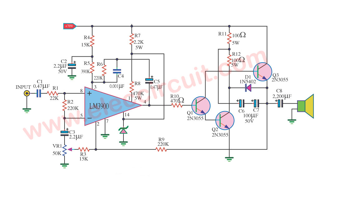
This be power amp OTL 50Watt use IC LM3900 and 2N3055 x 3pcs transistors to pillar equipment. Follow very circuit keeps to are Class ab then have a voice good loud. When , be amp OTL you then are certain that build easy use power supply the group is one 70V sizes by must use Current low 2Amp go up. Then have a voice good another thing you will like that amplifier. This durability do not make a loudspeaker a lose easy. The detail is other see in the circuit and model PCB next.
We like a 2N3055 Power Amplifier Circuit. Although it is the very ancient transistors, but it still have a lot of classic and very good sound. It is popular forever, very cheap, easy to find, easy to use. We recommended the 2N3055 power amplifiers circuit with PCB list below!
30W OCL Integrated Amplifier with PCB
If you want to create the integrated power amplifier project for the first time.In addition, we will use ICs because It’s convenient and modern. But I often recommend this project 2N3055 amplifier circuit. The output power is 30 watts RMS, using all transistors. You may like it.
Read more: 30w OCL integrated amp with PCB
40W OCL transistors Main Amplifier circuit
This circuit is one that stands out for ages over 40 years, with sound quality that is hard to find compared be other circuits. If you experimental build or ask people who try already built. Will believe that this is not an exaggerated statement more than true. Read more: 40W transistors audio amplifier circuit
50W OCL main amplifier using LF351-2N3055-MJ2955 with PCB
This 50W OCL main amplifier circuit has high quality,economical and also easy to build too. Because it is designed simple, It can be easily created in your friends, An electronics rookie. And cheap when compared to other speakers, the as same volume level.
100W power amplifier OCL
Related Posts
I love electronic circuit. I will collect a lot circuit electronic for teach my son and are useful for everyone.
Very, very interesting collection of very fine circuit diagrams.I have no doubt whatsoever by studying the circuits and having dabbled with many similiar circuits in my college days, I can vouch authoritatively hat these circuits should by and large should work splendidly without any problems. One point 2b noted plz. These circuits have very little technical explanations included in order2 help the uninitiated.there is also 1 other problem with the language, although the author does try is best , vr sure he or she is not able2 put his thoughts across completely.I would like 2 help u here, These Hi powered amplifiers have a few imp points2 note like these circuits have 2b assembled rather neatly with spl emphasis on taking care of Earth loops…Never heard of it? The assembled project even if wired correct would almost blow the opt devices(along with the connected speakers)if care is not taken 2avoid el probs. All it means do not mix (Esp Preamp signals With opt signals & pz try 2 ensure that the earth or ground (Often In common cases The Negative side of the circuit, And do note it is the Common Mid point used in split pwr supplies. Do realize the diff between the 2 & apply it diligently in practice. U may b surprised 2 learn how many of them make thes mistakes leading 2 costly loss of Time & Costly semicons that took a huge effort2 install & execute(:-(…often leading 2 severe disillusionment after powering them up. Best Of luck N sorry 4 SMS like Eng(:-)..)
Hi sir,
Its just great,thanks alot for sharing.
i want to pcb or complet kit LF351/2N3055/MJ2955 amplifier
Hello,
sir pl. send catalauge or price PCB of 60W RMS OTL integrated audio amplifier circuit full detail.
I see you don’t monetize your page, don’t waste your traffic,
you can earn extra bucks every month because you’ve
got hi quality content. If you want to know how to make extra money, search for: Mrdalekjd methods for
$$$
👍👍👍