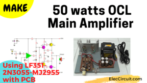
Do you like listening to soft music all day in your private room? On a budget that is cost-effective. I suggest you build a transistor audio amplifier circuit. This may be one of the best choices for you. Why? They are OCL class AB amplifiers using 2N3055+MJ2955 is easy to build, and very inexpensive.
To use Power Supply +35V -35V 2A. Transistor 2N3055+MJ2955 must be mounted on a heatsink. Can be directly connected to CD players, tuners, and tape recorders.
How it works
This circuit is one that stands out for ages over 40 years, with sound quality that is hard to find compared to other circuits. If you experimental build or ask people who try already built. Will believe that this is not an exaggerated statement more than true.
Recommended: Learn transistor circuit works here
This power amplifier series circuit, be able to output up to 40 watts on load 8 ohm and will provide an output capacity of up to 60-watt load 4 ohm.
The circuit design an All complementary all direct coupling (except the input), Making low-frequency response of the circuit well.
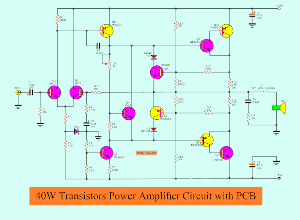
The transistor(MPS9632) Q1, Q2 together to as a differential amplifier, By has R10, R4 and C2 together constitute the feedback circuit and defined an all gain ratio of a circuit. At emitter circuit has Zener diode is connected as maintaining a constant voltage 15V.
The transistor Q5 is the part second amplifier circuit, by has C3 is to feedback between pin base and collector, to prevent procreation oscillator way high frequency
Q8, Q9 acting as the driver circuit to drives the power transistor Q10(MJ2955), Q11(2N3055).
For Q6, Q7 acts as the output transistor protection circuit from damage. Because the current flowing through the load too much. Such as a speaker cable short-circuited, by will acts as short the bias circuit of the output transistor is reduced so that it not works.
Q3 serves to limit current, the general bootstrapped circuit that uses the RC. for Q4 acts as setting bias level of the output transistor which is instead Diodes same the normal amplifier circuit. This connection reduces crossover distortion as well.
VR1 serves as to adjust a bias voltage of the idle current to the circuit.
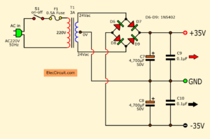
35V OCL amplifier Dual DC power supply
Here is a power supply circuit of a 40W-50W OCL amplifier. It is a 35V 4A Dual DC power supply circuit. The output is +35V, GND, -35V terminal. A circuit Designer set in an unregulated power supply pattern. This is enough for this case.
How it works
First of all, the AC voltage comes to a step-down transformer T1 through S1 on-off switch and Fuse F1. The T1 changes AC220V—120VAC in the USA—into about 24V+24V = 48V.
Parts You will need
Q1,Q2,Q3: MPS9632_Transistors, Bipolar, Si NPN Low-Power Audio Frequency Small Signal Transistors or…
Replace Part is BC167, BC171, BC182, BC237, BC547
Q3,Q6,Q9: MPSA06_NPN general purpose transistor or
Replace Part : BC 639, 2SD667, 2SD1226, 2SD1616A
Q5,Q7,Q8: MPSA56_Small Signal General Purpose PNP or
Replace Part : BC 640, 2SB647, 2SB910, 2SB1116A
Q10: MJ2955
Q9: 2N3055
ZD1: 15V 0.5W_zener diode
D1,D2: 1N4148_75V 150mA Diodes
0.25W Resistors tolerance: ±5%
R1,R10,R13,R14: 10K
R2: 7.5K
R3: 3.3K
R4: 470Ω
R5: 27K
R6 , R8: 1.2K
R7: 150Ω
R9: 680Ω
R11, R12: 100Ω
R15, R16: 220Ω
R17, R18: 0.5Ω 2W Resistor
R19: 10Ω 1W Resistor
P1: 1K Potentiometer
Electrolytic Capacitors
C1: 10uF 16V
C2: 47uF 16V
C5,C6: 47uF 50V
Polyester Capacitor
C3: 680pF 50V, Polyester Capacitor
C4: 0.1uF 63V, Polyester Capacitor
L1 use #24 copper wire on-air coil 5mm.
2SA1248=2SA1249=SAB649
2SC3116=2SC3116=2SC3117=2SD669
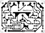
PCB layout
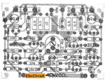
Component layout
Customization this circuit.
When this project is done, not to the speaker cable, adjust VR1 at the center. And then the power supply to the circuit, to measure at output point as the loudspeaker with the ground Should be less than 0V or 0.1V.
Then uses the voltmeter to measure the voltage across R17, as with adjusting the VR1 slowly until you read 0.01V Or may be adjusted by measuring the Idle current is about 15-30mA.
And then, connect the speakers, and input single to use work immediately.
Download This Post as a PDF and all PCB layouts
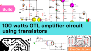
Keep reading: 100W OCL Power Amplifier
Do no see if you like small!

Related Posts


I love electronics. I have been learning about them through creating simple electronic circuits or small projects. And now I am also having my children do the same. Nevertheless, I hope you found the experiences we shared on this site useful and fulfilling.
need computation for 40 watts amplifier…..asap
hi!
Is This stereo, or only for 1 channel??
Hi,rafael
thank your comment,this is ocl 40watts use transistors.
old circuit but worked well. nice sound.
Hi, Ritvars.
This is mono system. If you need to use stereo, you must make them on two sets.(next one)
i compiled it,but give noise
but sound is good and have less base
ok.very good.
ahmad.from iran
Yes ,
This is very very good circuit,
No noise
High base
High sound quality
Hi, just followed the circuit but when tested on a 24V dual phase power, the C5 capacitor is burnt… it’s working on 12-V though… please help me how to fix it… thanks.
could not complete due to p0wer supply
Hello May I Ask for the Computations of this Circuit . thank you so much
hi
I noticed that are differences between schematic and pcb. I couldn’t find the 100k resistor in the schematic. There are four 0.5 R resistors on the pcb but only two in the schematic. I’ve made the pcb but I don’t know now what should I follow: schematic or pcb. Please give me a little help with this
Sir, how can I get 2 PCBs for the – 40W Amp OCL 2N3055 +MJ2955 ?
R6 in circuit was 1.2K but in board was 12K.
R10 in circuit was 10K but in bord was 100K.
In board had 100 ohms resistor but in circuit had not.
Is 24 the number of turns fof the coil?
Also, for R17 and R18 can I use 0.47Ω resistor instead of the 0.5Ω? I can’t find those on my local store.
Thanks!
Hello Miguel,
I am happy that you like this circuit.
Yes, you can use 24 AWG for coil output.
Also, you can use 0.47ohms.
Sometimes I will use two 1 ohms in parallel. It will get a resistance of 0.5 ohms.
Good luck and happy
Apichet
This is Phillips original circuit actually three is 3 pcb
Stabilized power supply bord
Universal preamp bord
Power amplifier bord
Three is also a book about this with all technical details from Holland Phillips labs
For best sound quality use shield wires for bass treble volume & input output
Driver transistor bass voltage is 01 volt ( adjust the variable resistance)
Use BEL 2N3055 if is available
This is the best amplifier you can have
I made this 40 years ago still is in perfect condition
Hi Babu
We are in the same era. LOL! So glad we’ve built this circuit.
Have a great day,