If you are looking for a high quality 24V PWM Motor controller circuits. We have many circuits for you. But today I am going to show you. Using TL494 and IRF1405 may be better for your choice.
Why it is special. Imagine the circuit has the low voltage battery checker system, working with soft start, adjust pulse frequency, and using for 12V or 24V battery at current up to 20A.
And it is small and simple. Not need to program software(without microcontroller).
It uses TL494, HEXFET and LM2940 as main.
There are 3 Circuits below!
12V DC motor speed control PWM circuit using TL494
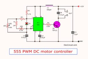
This is a 12V DC motor speed control PWM circuit. Which using a TL494 (Switchmode Pulse Width Modulation Control IC) is a base for control DC Motor with pulse.
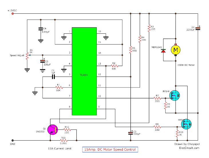
Please detail more:
– For Control speed motor 12V 150Wmax 15A.
– R6 adjust speed motor.
– Driver Motor by Mosfet IRFZ48.x 2pcs.
– Control at Frequency 100HZ
– Adjust PWM duty cycle From 0 to 100%
– Rise and fall time = 10uS
– There is over load current 15A or current limit with current flowing throw R11 and Q1 work to stop IC1
12V-24V PWM Motor controller circuit using TL494 and IRF1405
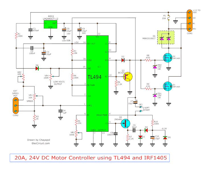
The working of circuit
Fig:1 Schematic diagram of this projects.
Project features
– Power supply range : 12V to 30V
– Current usage: maximum at 20A
– Current output : Maximum at 20A
– Standby current : 20mA
– Motor controller: 0 to 100%
– Cut off working when lower battery voltage: As setting at 11.5V for 12V and 23V for 24V battery.
– Adjusting pulse frequency: about 100Hz to 1.1 Khz(129 Hz to 1.28 Khz in this projects)
– Soft start: between 0 to 100% in range lower than 1 second
Pulse rising-edge and falling-edge at the gate of MOSFET: 1.5uS and 1.6uS
-VR1:speed controlled
-VR4: Low voltage output protection
-VR3-adjust the pulse frequency output
-VR2-sub speed controller
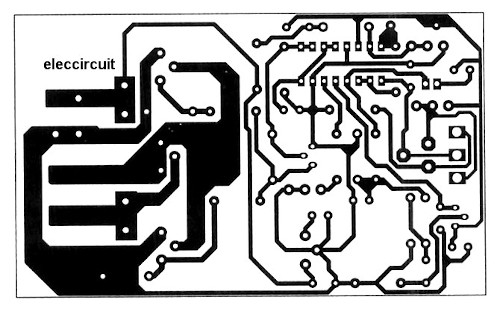
Fig:2 The Copper PCB layout
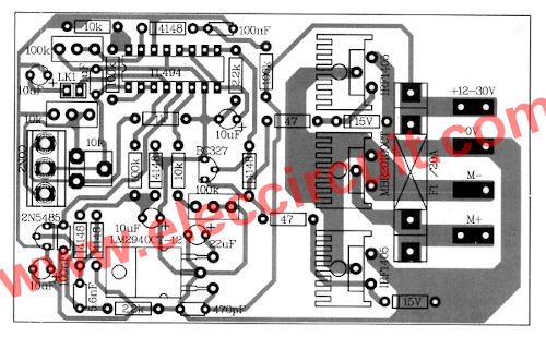
Fig:3 The components layout of this project.
Note:
My friend sent me this circuit. He said it is a very good high current DC motor controller. But it is a full article and not a clear photo.
Parts will you need
- IC1: TL494, Pulse width modulation(PWM)
- REG1: LM2940CT-12, Regulator
- Q1, Q2: IRF1405, N-channel MOSFET
- Q3: BC327, 45V 800mA PNP Transistor
- Q4: 2N5484, N-Channel FET
- D1: MBR20100CT, High-frequency Diode
- D2-D6: 1N4148, 75V 0.15A Diodes
- ZD1,ZD2: 1N4744, Zener Diode
Capacitors
- C5: 22uF 16V, Electrolytic
- C3,C6,C7,C10: 10uF 16V, Electrolytic
- C4: 1uF 63V, Ceramic
- C1: 470nF 63V, Polyester
- C2,C8: 100nF 63V, Polyester
- C9: 56nF 63V, Polyester
0.25W Resistors tolerance: 1%
- R1,R4,R10: 100K
- R3, R5: 10K
- R6, R7: 2.2K
- R2: 1K
- R8, R9: 47 ohms
- VR1: 10K Trimpot
- VR2: 10K Trimmer Potentiometers
- VR3, VR4: 100K Trimmer Potentiometers
- 10K Potentiometer
- The other parts, PCB, Heatsink, and more.
24V Motor control with 20A Short Circuit Protection
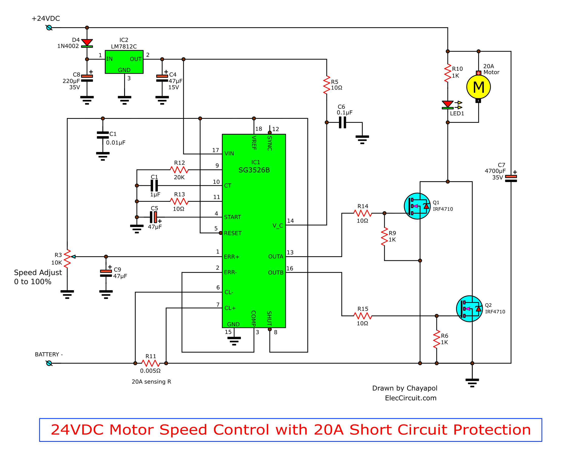
This is a 24V DC motor controller at the current 20Amp. By it uses IC SG3526B control in the character PWM that receive like very much and drive motor with power Mosfet number IRFP7410 x 2 pcs. Then can apply to DC Motor at use 20 Amp get comfortable and still have Shot Circuit Protection circuit As well. You see the detail adds at the circuit.
Recommended: How does a SCR thyristor work?
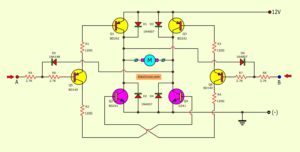
PWM Speed Rotation Forward-Reverse and Regenerative Braking
This is the PWM Speed DC motor Rotation circuit. It can Forward-Reverse and Regenerative Braking function. By this circuit used a signal PWM control the speed of DC 12V motor with Power MOSFET IRF150.
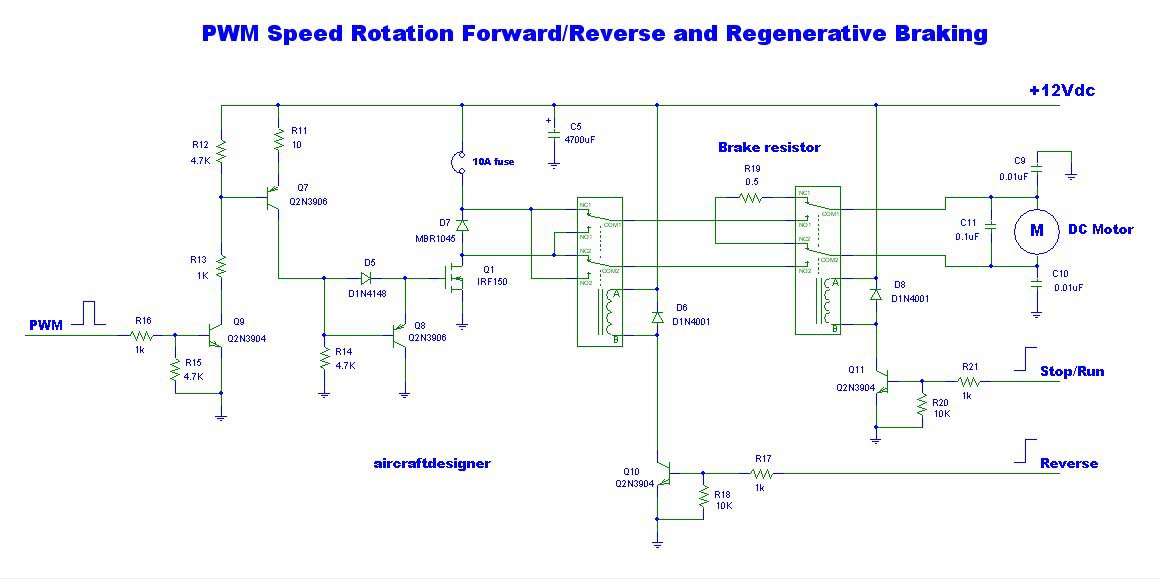
The relay RY1 uses control Reverse with the digital alarm, change, Q10. The Relay RY2 work be a function brake resistor. By control Run or stop with the digital alarm with. The F1, use protection through the circuit.
The D1 use to protect current turn back from DC Motor. The detail is other, please see in the circuit.
You may also like these:
- Simple 12V | 9V | 6V Motor DC Speed Control with PWM mode
- 555 PWM LED dimmer circuit diagram | Power Battery Saving
- SCR DC motor speed control circuit using IC-CMOS
Related Posts

I love electronics. I have been learning about them through creating simple electronic circuits or small projects. And now I am also having my children do the same. Nevertheless, I hope you found the experiences we shared on this site useful and fulfilling.
I will do it .I need Money because I am unemployed please respond to my e-mail you can trust me but I am doing for money please don’t mine I got e-mail f
Sir, I requseting we needed simple Automatic water pump control circuit doing.thats way I need your big positive help.. Please send that project or schematic. Thank you sir me waiting for your projects.
Hi murali,
Thanks for your feedback.
please look at :
https://www.eleccircuit.com/simple-automatic-water-level-controller-circuit/
https://www.eleccircuit.com/automatic-water-tank-using-pump-controller-by-2sd882/
https://www.eleccircuit.com/simple-high-level-water-alarm/
THERE IS MISTAKE IN PCB,ONE TRACE MISSING (CHECK LM2940CT-12 OUT to
22uf + to 10uf + to pin9,11,12 TL494)
Hi, thanks for circuit published, could you indicate – – what value to calibrate trimers?,
– how to connect motor, esxternal pot?
thanks in advance
omar
Hello! I would like to receive the file of the circuit board to manufacture the regulator. [email protected]
Hello! I would like to receive the file of the circuit board to manufacture the regulator.
This schematic does not work. There is a missing trace on the board (on the output pin of lm2940). One electrolytic capacitor has inverted polarity (c10). One ceramic capacitor has two different values in schematic file and board file (5.6nf and 56nf). Please someone respond.
# 12V DC motor speed control PWM circuit using TL494
Dear Sir ,
I am a hobbiest and retd electronic engr.Sir i found your [12V-24V PWM Motor controller circuit using TL494 and IRF1405] project .I want to buy the kit or assembled project ,kindly guide me where to approch for the same.
# 12V DC motor speed control PWM circuit using TL494
Hi
I need pwm that mines polarity of motor connect to GND directly . (I think must be used p-channel masfet)
## https://www.eleccircuit.com/pwm-control-speed-motor-12v-by-tl494
Dear Sir,
Hi – Do Tal IC 492 can be used to launch MOSFETs with high amp (200A) – out guide
## https://www.eleccircuit.com/pwm-control-speed-motor-12v-by-tl494
Dear Sir,
Hi – Do Tal IC 492 can be used to launch MOSFETs with high amp – out guide
## https://www.eleccircuit.com/pwm-control-speed-motor-12v-by-tl494
112/5000
Dear Sir,
Hi – Do Tal IC 492 can be used to launch MOSFETs with high amp – out guide
Hi Can you please explain what the circuit between the CT and DT pin ?
what is a “soft start LK1” in your circuit it is connect to DTC(dead time controller) pin .I did’t understand that sir!
pls help me sir!
[email protected]
are these circuits for brush type motors or for brushless motors
Hello DLC,
Thanks for interesting in these circuits. They are used for normal brush-type motors.
In the future, we will post brushless motors speed controller circuit.
Thanks
Could you provide me the design to control a 24v DC motor forward and reverse with tl494cn !!! excellent tutorial !!!
Hello Cesar Ramirez,
Thanks for your feedback.
can you explain why you use 2 mosfets?
Hello Nguyễn Minh Chiến,
Thanks for your visit. It is good, you are interested in this circuit.
As far as I know, the designer connects both MOSFETs in parallel to drive more current to load.
It increases the stability of the current.
Next, I will explain with illustrations to make it easier to understand.
Please wait for me.
Thanks