Do you want to know more about this simple inverter circuit? Capable of outputting 50 watts total with just a few components.
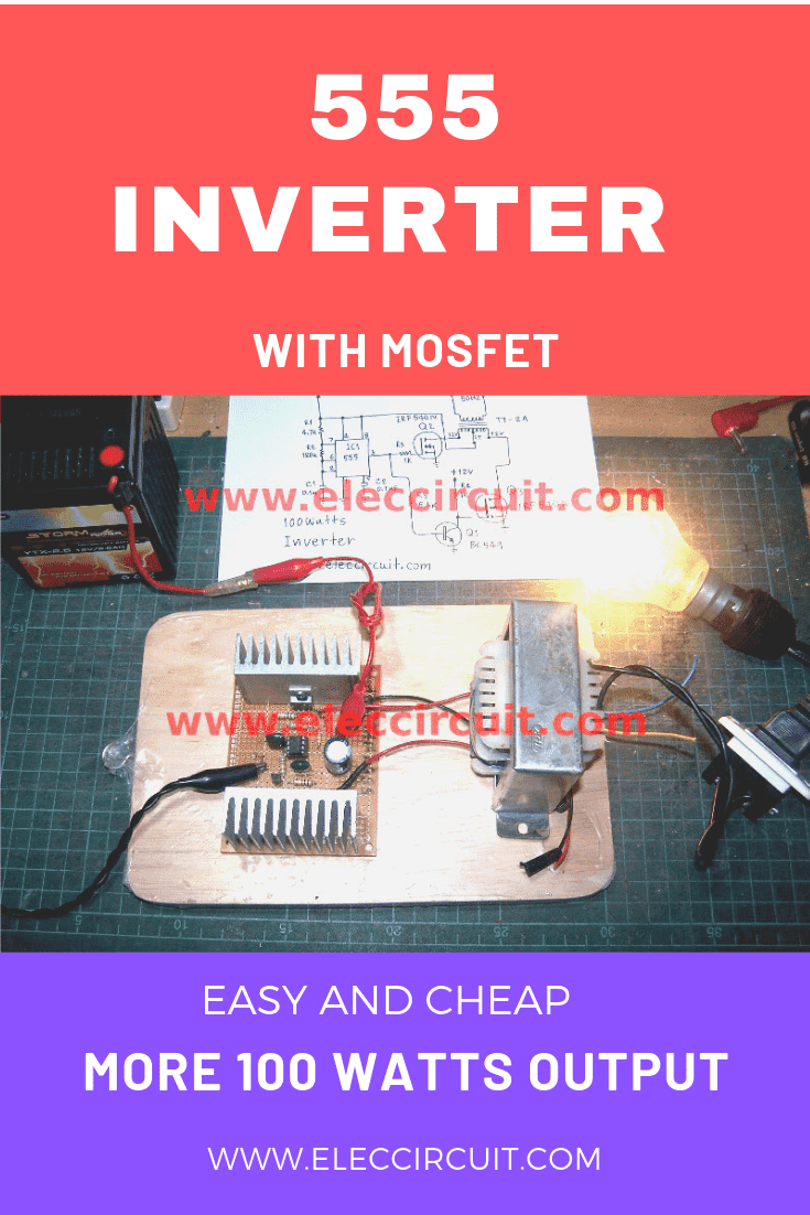
This is an IC 555 inverter circuit. Because of using the 555 TIMER and MOSFET as main. I experiment with it to work well.
When using a 12V battery as a source, it will output 220V AC 50Hz
The Basic Principle of the Circuit
We think most people do not like reading a long yet tedious explanation. So to keep it simple, we recommend: simple principle inverter
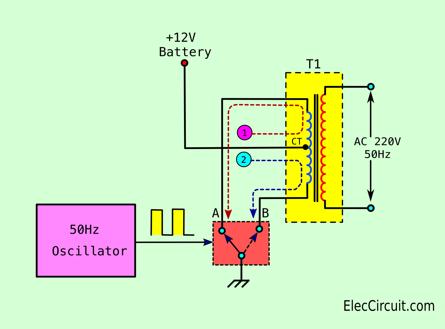
Initially, the DC voltage from the battery goes into a square wave oscillator circuit (50Hz Oscillator), producing 50Hz AC voltage. But the current is way too low.
Recommended: How does NE555 timer circuit work
What to do to raise the current?
In this case, power switching (A-B switch) such as power transistors or MOSFETs are one good choice.
But the AC voltage is still at 12V? The Transformer inductance will raise the voltage into
220V AC 50Hz, ready to be applied to a load.
How 555 inverter circuit works
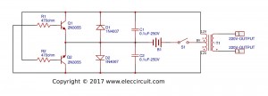
The circuit below is a complete circuit diagram of this project. I use the IC-NE555 timer is a square wave frequency generator output of 50Hz.
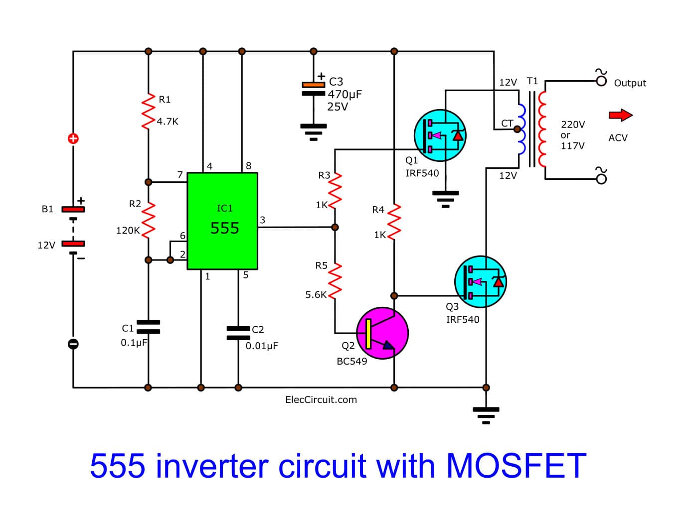
The frequency is determined by the R2 Resistor and C1 Capacitor.
555’s Output Frequency Calculation
If your R2 is 150K, then the output is 47Hz. You may add a potentiometer to fine-tune it to 50Hz later down the line.
MF4Me said: By calculation (results will vary depending on the component tolerances) a good combo of common parts would be:
- 0.2 μF (2 x 0.1 in parallel)
- 100Ω for R1
- 72K (39K and 33K in series) for R2.
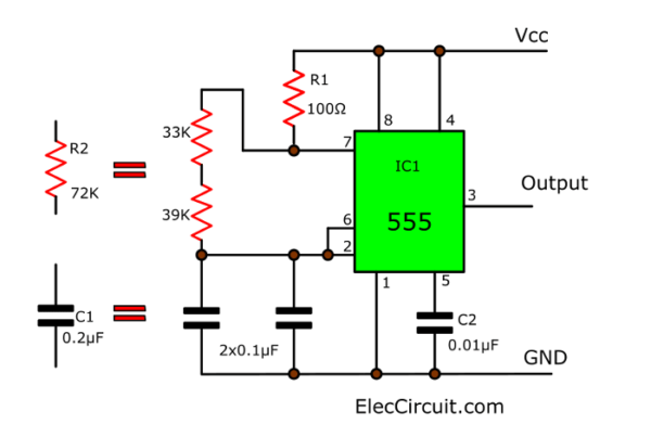
The calculation result is 50.069 Hz with a 50.03 duty cycle. That is smart accuracy. If its tolerances are low.
What is more?
We use N-type MOSFET IRF540 (Q2, Q3) to drive a transformer coil (primary winding).
The output current at Pin 3 of IC1 will flow in two ways.
- First, through R3 to a gate of Q2.
- Second, flows to Q1-transistor BC549 as inverter logic form to reverse signal difference first ways.
Next, the current flows to the gate of Q3 to also drive the transformer.
It inducted low voltage to high voltage, from about 220V to 250V depending on the battery (12V to 14.4V).
The circuit diagram of the MOSFET Inverter
For the transformer, I use 2A of current, if a 12V input voltage. It causes the output power to be more than 100 watts.
Here are a few related posts you may find helpful, too:
- 1.5V to 220V Simple Inverter circuit
- 500W MOSFET Inverter
- How to make simple inverter circuit diagram within 5 minutes
Why use MOSFET?
In the circuit, we use IRF540 MOSFET. There are many reasons to use them.
- It is easy to use. They do not need the pre-drive transistor in Darlington to be the same as normal transistors, such as TIP41, 2SC1061, etc.
- It can drive a high current load, 27A max. While the TIP41 transistor can only drive a 4A load.
- It is inexpensive, just 0.8USD per pc.
- The body is similar to a TIP41 transistor, so it is easy to mount to a heatsink.
- They can be mounted to a smaller heatsink than a transistor, because of their low heat output.
The component list
IC1: NE555 timer IC = 1 pcs.
Q1: BC549-NPN 40V 0.5A transistors = 1 pcs.
Q2, Q3: IRF540-N CHANNEL POWER MOSFET, 100V, 27A, TO-220; 2 pcs.
C1,C2: 0.1uF 100V mylar capacitors = 2 pcs.
0.5W resistor
R1: 4.7K = 1 pcs.
R2: 120K = 1 pcs.
R3,R4: 1K = 2 pcs.
R5: 5.6K = 1 pcs.
T1: 2A 12V CT 12V transformer = 1 pcs.
Heatsink
Building and testing of 555 inverter circuit using MOSFET
In this project, I assemble components on a universal PCB board. As Figure 2, while operating it will get a little hot. So be sure to use enough heatsink.
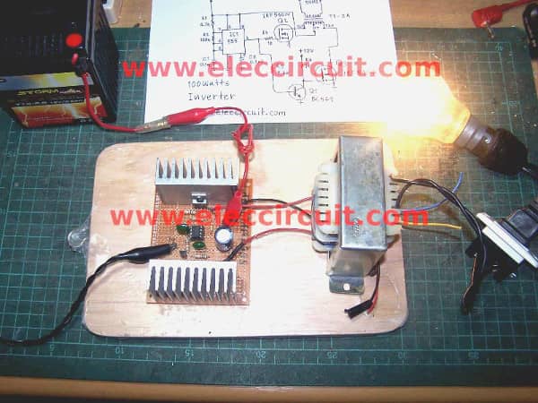
Figure 2
Then, check the circuit for errors. Please watch the video below.
When checking all no error
We will test it with a 100 watts lamp at the output, with a 12V battery as a source. You will see that the lamp glows. But the battery voltage is slightly low, so the AC voltage output is 190V.
After that, We check waveform is a square wave as shown on the scope.
Note:
Some people wonder about something. I will share it with you.
I put the 470uF 50V electrolytic capacitors to filter the current.
It does not need if you use a 12V 10Ah battery. Because it is a stable power current source.
Ideally, if you need full 100 watts output. You need to use 8A transformer. Because of input watts = output watts = 100 watts.
When the primary coil voltage of the transformer is 12V at 100 watts.
The output current input = 100W/12V = 8A (approximately)
If it not working
I feel bad if you have built this project and it does not work.
First, you need to review the pin of the IC, resistors, and
capacitors. And importantly is how you connect the MOSFET.
Second, should do not connect the power cord to the transformer and MOSFET.
Third, check the 555 timers working, and frequency generators at pin 3 first. You may use a voltmeter to measure a voltage across pin 3 and the ground. You use surely oscilloscope to watch waveform.
Check out these related articles, too:
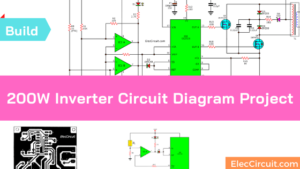
- 200W Power Inverter Circuit
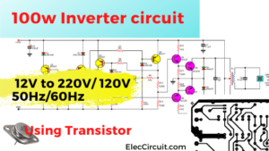
- 100w Inverter circuit 12V to 220V using Transistor
- Simple inverter circuit using 6 transistors

Related Posts

I love electronics. I have been learning about them through creating simple electronic circuits or small projects. And now I am also having my children do the same. Nevertheless, I hope you found the experiences we shared on this site useful and fulfilling.
Nice. I will try it soon. ThanQ for publication
Very interesting, but I build K-bridge not center-tap.
nice work any way
estimado amigo gracias por los envios de sus proyectos son muy util
Saludos
Hi,RK Chall
Thanks for your feedback.
Hi,Francisco Mateu
Thanks for your feedback.
thanks for sharing the circuit
is there a simple way to make some changes to make the frequency adjustable?
with a potentiometer or something?
grate work
Hi serunkuma shem.
Thanks for your feed back.
hi.sir thanks for inverter circuit.plz tell me another transistors if I don’t find irf540???
I love your work,it is great though i have nov tried it. But is the wave a square or sine. Thanks. Elijah
Sir,when i calculated the frequency using F= 1 / 0.693 * C * ( Ra + 2Rb ) ,where Ra = 4.7K , Rb = 120k and C = 0.1u , i got 58.97Hz instead of 50Hz. Please help me. Thanks
Hello sir.. Im trying to make this inverter using all the component listed in the above section, but i fail to produce th 220v ac.. I just want to ask.. Is there any unlisted component because when i look closer to ur circuit, there is a big black capacitor-like component. I hope u can explain about it.. Tq!
i am searching for a simple easy inverter circuit & i get this i am so intersted i will made it to day…
the transformer whish is using is a normal transformer 220v to 12v or not…
i tried to make it but my 555 burded out and brust ed why ??
Hi, Sk sahabaj
Thanks for feedback.
Yes, your correct transformer.
Hi,sanjed arfin
I am sorry for your IC burded.
You should check pin of IC-555 it may short or incorrect places.
Thanks for you feed back.
c2 should be .01uf otherwise it will burn.
Hi,Sanjed arfin.
Thanks for feedback.
C2 is 0.01uF to 0.1uF it not burned.
I test really them.
Hi,Mansoor
Thanks for your feedback.
This circuit works surely.
as video is shown.
Hi,ErHonni.
Thanks for your feedback.
Yes, you can use potentiometer for adjust output frequency.
Hi,RK Chall.
Thanks for your feedback.
Hi,Mark.
Thanks for your feedback.
What about K-bridge?
Please tell me.
Hi,Francisco Mateu… My friend
Thanks for your feedback.
Hi,serunkuma shem
Thanks for your feedback.
Hi,Elijah
Thanks for your feedback.
The output is square wave at around 50HZ-60HZ
You may use potentiomer for adjust frequency.
i can’t find irf540 please tell me the alternative of irf540..
@sk sahabaj.
IRF540 is N channel MOSFET that you can you any Mosfet which high current and voltage 33A 100V. I like it because very cheaper and easy to buy.
hi what can i do to increase the out put power to 200w
Hi,V
Thanks for your feedback.
You can add Mosfet in parallel to increase current driver transformer which must change is 2 times current.
hi admin thank u very much for your replay ,can u tell me how to add mosfets in parallel
Hi, V
You can add mosfets in parallel for increase current drive secondary coil of transformer.
do you think adding mosfets will increase the output power effectively
Hi,vasudev
For me if add mosfet in parallel it will increase current to higher.
I should this mosfet because cheaper and easy to buy.
hi momename
can i use ne556 instead of ne555,because it is more efficient than ne555
hi sorry it is not ne556 it is ne7555 which is cosmos ic
@vasudev
Yes you can use NE7555 same NE555.
hi according to the power relation p=i*v ,where i is current & v is voltage
but here if we use 12-ct-12v 2amps transformer we get only 24w of output how can we get 100watts of output power (p=2amp*12volts
=24watts) ???
@vasudev
I do not very good any principles,But I love Electronic, If I test it works, I will tell you.
> Hi good friends,i have a ups with 24v battery and wont to convert it to
> inventer to power my 110v fridge thank you.
>
Hi, James Abeaku okine
I not have a 12V to 110V inverter circuit example show you.
If you have free time you may be test your ups circuit.
and modify them.
or you may remove the transformer.
To adapt circuit into this circuit https://www.eleccircuit.com/220-volts-power-inverter-using-ne555-and-mosfet/
But you must to use zener diode or IC7812 to reduce voltage of 24V battery to 12V to supply the IC555 only.
I am sorry for circuit ideas (in image form) since now I take my family to weekend Holiday.
Thanks
Momename
hi momename does the increase in gate current increases the output power
hello Admin,
I have made d circuit and every thing is ok…but when i put the +ve terminal its sparks and flash the 220V 20W bulb while one of the mosfets becomes very very hot and starts smoking.
Pls help ….thanks
In the picture on the website, you used an electrolytic capacitor…?
Hi,vasudev
You may increase current drive transformer with add mosfet next one in parallel.
Hi,Charles.
Thanks for your feedback.
Please check connection of mosfet, they may wrong lead.
hai momename
can we use it for fan in home?
what will be the output if i connect 12v/ 70AH
and i need ahelp for making an 1500W inverter
please tall me meaning of ct
Work but 60 watt bulb is very dim not full
Hi,saurabh
Thanks for your feedback.
If you need full watt ouput.
You must use 100W = 12V x I? transformer.
or 8.3A input transformer.
Using 3 capasitor and what diagram of third capasitor
what will be the output if i connect 12v/ 70AH
and i need ahelp for making an 1500W inverter
When battery is connected bc549 getting hot no out put voltage solution pls.
Hi momename, if iput more mosfet in parralal can it increase wattege my requerement is 800w
Hi,saurabh
The third capacitor is filter for low current battery.
We not need put in the circuit.
Hi,Mr.Surasak
Thanks for visit.
If you want fully power 1500w.
You need to use 125A too current for me.
and this circuit is square wave ouput.
cannot use for motor load.
Hi,Kingshuk
Please BC549’s lead and the circuit again.
Yes, If you connecte more mosfet in parrallel it can drive very many current load.
Hi Momename
If I connect the 8.3A transformer, then should I increase the no. of mosfet, or may I use the 8.3A 12V 100w transformer with the same circuit. Pls let me know ASAP..
Hi,Anjan Chatterjee
Thanks for visit.
Ideally, the mosfet can drive 27A maximum.
But we may connect them in parallel x4 pcs.
Normal current each mosfet is 2A so easy to drive load.
If this project work please send your photo to me.
Thanks for your kind feedback Momename. I actually want to use this circuit as a travelling battery charger(phone, dslr)where I connect solar panel (12V, 70-80watt) as source. I will connect the battery charger as load, I think the charger don’t get to much watt. So I think I easily use this circuit. **Pls correct me If I am wrong..
Thanks..
*should I send My photo or the mentioned project photo ?
Hi, Anjan Chatterjee
It is good idea. your project is very large.
You should will use battery charger controller.
In my project is small size so not need this circuit.
https://www.eleccircuit.com/automatic-led-night-light-switch/
___ You can send email to me [email protected]
Thanks for your feedback.
Hi momename
Thanks for your feedback..I previously checked that project. But I don’t want to carry the battery. I thought I simply connect the 12v 7-8ah solar panel directly with your this circuit(source). If I do so then will the circuit work ? I dont need power at night.
Thanks A lot for helping me…
Hi In your circuit diagram you mention Two +12 volt Dc Terminal/Point. But In your Figure 2 You put Providing +12 Volt Dc Only one Point. Can You Pls Tell Me Is The Diagram Right ? Should I provide +12 in both terminal or should I Provide +12V in one & another with -12V. And Pls also mention the points where I have to provide The +/-12 Volt in the circuit.
waiting for your reply..
Thanks..
In place of bc549 transistor can I use bc547 ???
Hi,Salkat
Yes,you can use it BC547 same BC549 or similar: BC550,BC546, etc.
Hi,Anjan Chatterjee
In Figure circuit diagram.
All ground is (-12V terminal)
All +12V are joint together = +12V.
If i use 8 amp of transformer then i have to use 2 pair of mosfet?
how many power i will get after doing this…
Pls ans me as soon as possible,,,,…….
And through this circuit can i run a motor of 80 watt?
is it okay. If i use power bjts tip122 in place of mosfets.. Will the output varry?
Hi,Saikat,
Yes, you can.
Hi,prits
Thanks for your feedback.
If you ue transistor, you should too many transistors.
In this case you may use darington transistors.
Dear Sir,
I have build this circuit and it works absolutely fine. Kindly suggest me a battery charger circuit which i could use with this circuit and if possible suggest me how to convert this square wave inverter to a sine wave inverter.
Regards,
Santanu Dey
Very simple Example of inverter working principle, thank you so much sir. small doubt sir instead of single transformer can we use 2 transformers in series? please rectify my doubt
Hi,Santanu Dey
Thanks for your feedback.
Now I not have how to convert square wave to sine wave.
When I have it will fast post to you.
Dear Sir,
Thanks for your reply. Could you suggest me a battery (12v/7.2AH) charger circuit which I could use along with this inverter circuit.
Regards,
Santanu Dey
hi all,if i use a 50Amps transformer will the circuit still work fine,P=IV so 500W=I x 12v which gives 50Amps & also what if i use pair of transformers in series.
Dear Sir,
Could you tell me if I want use that 470uf electrolytic capacitor, where should I place that in diagram?
Could you send me the new diagram with that capacitor or your PCB and schematic files?
Regards,
Hi sir, am asking why is Q2 very hot and Q3 very cold and vey low output of 30V.
Thanks for your display and article.pls do you have avenue on seminal or training for any intrested person
Hi,Taofiki I Akinleye
Thanks for your feedback.
Why is not working I use MOSFET irf3710
Can I use a power supply as my input?but why my voltage source breakdown to 6 volt
Hi admin..why may Q2 has no out voltage while the Q3 has output voltage of 12v
sir…wt s the cost of 12 volt battery and the cost of transformer……thankyou
Hi, mhafe
Thanks for feedback.
This circuit used for 12v battery.
Q1 make volage different 180 degree.
To drive transformer.
hi sir can i use irfz44n instead of irf540?
Hi, joremie
Thanks for your feedback.
Yes, it can be use if n types.
thanks for your reply sir., sir do you have a diagram of a pure sine wave inverter?
Can I use 24v as a battery voltage in this circuit?? Please response first I’m on it .
i have make this circuit. but this circuit is not working probably. the main problem is that ic only gives the positive voltage and does not give ground so can you plz solve the problem. what is the problem with pin 3 or ic? plz reply i am waiting for your reply.
Hi, did you check how much efficient is this circuit how much watts draws at primary winding and how much provides at secondary winding
470mf where he would have to be connected resistors 0.5W
Sir,thanks for the circuit. I want to know the advantage of a sine wave over a square wave inverter. Please help me. Elijah
Sir you dont mention the connection of heat sink in your ckt diagram
How can i connect it
iam very happy with this, but sir the two types of the inverters i make them no any problem but sir they can’t take RED Globe.plc sir can we start communicating in other to help me with some or many ideas thanks so much (+2347064396921)
sir you dont mension the capacitor at the battery terminal side and it is very important one ,so i got the output correctly .
Dies ist eine wirklich interessante Schaltung. Sie sollten diese zum PATENT anmelden. Der Wirkungsgrad von mehr als 400 Prozent ist wirklich bemerkenswert. ‘The transformer I use 2A current and 12V input at output power more than 100 watts.’
Erreichen Sie diesen hohen Wirkungsgrad durch die unsymmetrische Ansteuerung des Transformators?
Ich habe da einen Vorschlag für Sie. Erzeugen Sie aus den 220V wieder die 12V Speisespannung. Sie haben dann noch genug Energie über, die Sie weiter verwenden können. Gehen Sie aber sicher, daß Sie alle überschüssige Energie entnehmen. Ansonsten könnte ihnen die Schaltung aufgrund des Energieüberschusses explodieren.
Viel Spaß, Baltuodis.
Plz sir i want to construct a 1000watt 12VDC-220VAC inverter, (normal and fast) charging plus mosfet and circuit all on P.C.B Module i nid ur help
Dear You did it I will try
VERY high losses in mosfet`s and poor efficiency!
how sure is this circuit because i have build some many circuit from the internet not 1 worked.so pl’s will this circuit work?
is the transformer used a normal 230v to 12-0-12 connected as reverse or is this a special step up transformer?
hi
at first thanks for this simple circuit.bt i have a problem.from this circuit i get square wave form.bt output voltage is very small,in mv.please give me a proper solution.it is very urgent.
i made this, but it isn’t working. their is no drain voltage. what is the problem. plz let me know.
respected sir
how to cheack mosfet and fet ?what is3171 in ups
great project thanks
Hi my friend,
Thanks for your feedback.
i want to know output and working of each component.hw dc is converting into ac,hw mosfet works.wt output thy give..coplete function of each components along wid output
Hi Bhader singh,
Thanks your question. Please read : https://www.eleccircuit.com/simple-working-principle-of-the-inverters/
Hi I want to build a inverter few year ago but i can’t find a easy to build circuit.But now i find this assome circuit.Now i can build this.
Thanks for the project.
pls sir, your circuit worked well but I discovered that when I added more load, d voltage decreased. how can we make up for this pls? I believe if we can initiate a feedback unit, it will solve this problem. so where and how do we apply the feedback pls? work on this because its necessary sir.
pls sir I want to construct a 12v inverter, u need a circuit diagram
pls sir I want to construct a 12v inverter, i need
a circuit diagram
I want to build up a 220 volt dc to 220 volt ac inverter
Sir, which is transformer is used in this project step up or step downh . please tell me
this circuit is very good. i tried it …it works good but very less efficiency..
q2 is very hot but q3 is very cool…may i know the reason please…i have used 3 amp 12-0-12 transformer.
tq
He said possible draw or sketch Print
i love this site.more power to your elbow
Hi sir, i saw ur project as simple and I feel in love with it,so I decided to practicalise it.I used IRF2807 instead of IRF540N and BC547 instead of BC549 bt the bulb jst light on for a few seconds n went off.since then I’ve been troubleshooting it bt cnt find where the problem lies.pls cn u help me with a solution ASAP.I really need it
Hi sir,can I use 30amp as power mosfet such as FDB7030BL or CEP7060R?
Sir can do a video of this on a breadboard (temp white board) because i ve tried the circuit it didn’t work i need ur coaching
love your work ! can you send me your wiring layout to [email protected] ! always here to support your product !
Can I change 0.1uF to 104
Can i use this square wave inverter to charge my phone..??
got 200v o/p only 🙁 how to make 230v o/p
help me plsss
Why used BC549 transistor
Hi Vidyasagar Mandal,
Thanks for your feedback.
The BC549 is cheap and easy to buy.
Hi adarsh,
Thanks for you question.
You may try to use a transformer; 9V to 10V for input and 230V output.
IC 555 Timer Calculator with formulas & Equations IC 555 Timer Calculator with formulas & Equations IC 555 Timer Calculator with formulas & Equations
Formulas and Equations for This calculator
Frequency (f) = 1/ [ ln(2) x C x (R1 + 2R2) ]
Frequency (f) = 1.44 / C x (R1 + 2R2) …. Where… 1/ ln(2) = 1.44
This formula putting and get 58.9hz frequency in output 3no. pin on 555 ic why this inverter out frequency 50 hz
AWESOME!!!
I made it but it gives me low voltage 40V AC
I made this circuit …but the output from the MOSFETs have only one output at a time ..Both MOSFETs don’t get ON simultaneously …What to do ..I have used BC 547 in place of BC 549
My circuit is working but the only problem is that when i reomove and again give ground then bulb blinks but it doesnt remained ON … what can i do? please help asap!
so very high tech the inverter by MOSFET perform the working 12dc to 230 ac
you use 470mf,50v capacitor where it would be connected…please reply asap
Am still arranging d cct together I will get back to u
I use bc547 but I notice it’s only one get switch but d other fet is off d volt frm 5.6k didn’t feed the 547 pls what should u do thanks
Can i use a car battery???
Thise circuit is’t work. Real time simulation faild to start
in the image of this project there is a capacitor but it is not mentioned in its circuit diagram. why?
I already build the ckt the problem is the other mosfet is heating…and the output is onl 50volts AC
Can you help me…what is the problem?
finally!! After so long it worked. hey guys, one extra capacitor(470uf, 50v) is used in the circuit is important. it is used as a filter and you can connect its negative and positive through the dc supply’s -ve and +ve respectively.
NOTE: It do not required, if you use 12V battery 10Ah because it is stable power current source.
i made the circuit properly as mentioned ,every components are of equal as given value but it is not generating 220v and transformer is heating very much .what to do please help me??
i made this circuit everything is placed correctly of right value but the circuit is not generating 220v ac and the transfermer also get heated very much.please help!!
If i want use 40 volts dc voltage as input voltage then what is the rating of all components like resister, capacitor etc….
Plz rpy me immediately…..
It’s work good with 750ma transformer when I connect 5A 12_0_12 v transformer the ic ne555 was heat much and burn
Can i use 3A 12v-0-12v transfomer for dis circuit
Hi bro, I like the concept you use to design circuit. I fabricate the same circuit with the same spec of all the component as you used but instead of using 12-0-12 2A transformer, I choose to use 12-0-12 4A transformer. In software simulation, I have tried using Multisim and Proteus. Sorry to say the simulation was failed. The result in real time hardware fabrication is a positive. I manage to light up a bulb but the waveform generate from oscilloscope is clamping not a square wave. The light which lights up keeps flicker. I used 12v 7.2AH battery. Did you manage to simulate this circuit in software? If so, please reply me. Thank you.
Please help.
Tell me the diagram that has 470 capacitor connections. My voltage is 100 volts. The first one is the project. I am weiting your ancestor … Please help.
what should be substitue to bc 549
pls help.
what should be substitue to bc 549
pls help.
what should be substitute to bc 549 because that transistor is not availble in my place.
hi
aim amirhosein from iran,tehran
tanks your website
its very very good
tanks
Hi amirhosein
Thanks for your feed back.
I connected the circuit as illustrated but whenever i connect it to the battery which is 12V 7Ah, the wires heat up and burn and no output from transformer. Please help
You project and website are very good and benefit for Electronic working.
Hi Aerk
Thanks your for your feed back.
Friend kaj holona to
Please can I use ups transformer?
Yes you can use it.
Thanks for your feed back.
Dude, either your cap is way out of tolerance or your math is off. A 4.7K resistor for R1 results in 58.97 Hz by calculation. If peeps are putting 60 Hz into a 50 Hz transformer, they’ll have problems.
Hi MF4Me,
Thank for your feedback. You are correct.
We can change R2 too. To set output is 50Hz.
YW. By calculation (results will vary depending on component tolerances) a good combo of common parts would be 0.2 uf (2 x 0.1 in parallel), 100 Ohm for R1 and 72K (39K and 33K in series) for R2. That calculates to 50.069 Hz with a 50.03 duty cycle. That’s smart bomb accuracy if your tolerances work out. Otherwise that should get folks close enough.
Wow! that’s nice. You are great.
Your design and calculations are excellent.
Thank you very much. It is will definitely benefit everyone.
Kya ya battery ko charge bhi KR sakta hai
Hello Rahul,
Thank you for visiting. You mean you use this circuit with your mobile battery charger again, right?
It may work. But…It is better. If you use 12V to 5V DC converter to charger the mobile directly.
See: https://www.eleccircuit.com/12v-to-5v-converter-step-down-3a-regulator/
Hope I will understand it correctly. If you finish this project do not forget to share me know too.
Can it work with a non-centre tap transformer
Hi Emmanuel
No, you cannot use for non-center tap transformer.
Hi,
Can i use sw50n06 instead of irf540 ?
i tried, but it’s getting heated unexpectedly.
Hi,
Yes, you can I just read datasheet of SW50N06: on TO-220
FeaturesN-Channel MOSFETBVDSS (Minimum)RDS(ON) (Maximum)IDQg (Typical)PD (@TC=25 ): 60 V: 0.023ohm: 50 A: 30 nc: 130 W
You may try it. Please cheack leg it again. I sure you can do it.
Hii, i have one doubt that this circuit output is 50hz sinusoidal or sqare wave? Please help me solve this problem, as i also wanted to charge my mobile phone using this and mobile charger required only sinusoidal input.
Thanks and regards
Hi,
This circuit does not suitable for any load that requires a sine wave source.
You may use the DC to DC converter 12V to 5V. https://www.eleccircuit.com/12v-to-5v-converter-step-down-3a-regulator/
It may is better than the inverter circuit.
Thanks
Sir this circuit output is 50Hz sinosoidal or sqare wave.
Hello Rishikesh Singh,
I am happy that you feel interested in this circuit. Its’ output is a square wave.
Thanks
Apichet