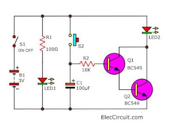
This circuit is based on learning of the discharge and charge of the C. This can be used as a timer circuit and can be applied in the OFF electrical appliances.
The application has also put relay instead of LED can be enabled.
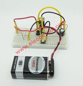
This circuit is working as video below:
How it works
When we press the switch S1. It causes LED1 to be light told state ready.
Then, we press S2, which is a timer switch. On the press switch, the S2 current will flow to the C1 charge fully.
Then, to discharge out through R2 to limit current. To flow to the bias for transistor Q1.
Both Q1 and Q2 work together in Darlington Compound mode. To increase the current higher gain to drive the LED2 light up.
The LED2 is still overtime as C1 discharges all Q1 and Q2 stops LED2 is off if you want the timer circuit is longer. Then add the C1 and if you want a little time. to reduce it to C1.
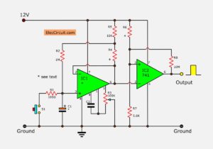
10 Second Fan ON Delay Timer circuit using transistor
A friend of mine wants a 10-second delay timer circuit at can turn ON Fan 12V at use in an automobile. By fixing the period of time by about 10 seconds. He sets conditions that must use electronic parts to economize and seek ease with.
I then choose transistors and relay controls electric fan equipment follow the circuit in a picture. The value delays can fix with R1 and C1 which there is a formula that calculates 0.5 x R1 x C1.
When press S1 wait for about a 10-second relay then work turn on give the electric fan works. The detail is other seen in the circuit.

Buy components in this projects HERE!


Related Posts

I love electronics. I have been learning about them through creating simple electronic circuits or small projects. And now I am also having my children do the same. Nevertheless, I hope you found the experiences we shared on this site useful and fulfilling.
I would like to know if I can you this circuit and would like a delay (LED on for 60 minutes) If I can use a bigger condenser and only one transistor?
thanks !
sir,i’m not getting the output
please help me
Hi,Abel
Thanks for your feedback.
Please try to replace C1 with 220uF capacitors.
It may times is 60 minuts as you want I am sorry that never test it with this value.
Hi,Suma
Thanks for feedback.
Please check circuit again on breadboard, such as lead of transistor or capacitors. Please slow… check. This circuit works great.
Hello, what if I want to add a small 5V relay, and power the circuit from 5V?
I would place the relay at led 2 position, including a diode across the coil.
Would this work?
can we use 12 volts instead of 3v and change value ofR1
if i can replace 12v.
Hi,
If 12V is used, will it change the 30 min to a shorter time? Thanks.
This won’t even do 30 seconds let alone 30 minutes.
@Storm
This circuit works although you may have to play with the capacitor values and resistor value at the base of the transistor. I got a different time for the same values.Also make sure your capacitor and transistors are working properly.
My question though is, if you push it and let go immediately versus push and hold for a few seconds and then let go. Will it make a difference in the time?
Ok so I found out when you push and hold the button for a few seconds and release, the timer goes even longer. Is there a way to make it the same time when you push and hold vs push and release? Thanks.
Need for adjustment timer
That is once start after a few minutes off the circuit connection
I want to make a circuit which is turn on light after 30 minute of switching
Hi I’m trying to do a timer with alarm every 30 min with buzzer on a 12v battery circuit.can you show me the diagram pls? Really appreciate. Thanks
Hello David,
Thanks for your visit. I am glad that you are interested in this circuit.
Your idea is great. I’m also wanting to build this circuit. But these days I’m very busy.
I am sorry. Please wait for me. Soon, I will prepare an article about this circuit for you.
Thanks